Method and apparatus for synchronizing data between different clock domains in a memory controller

a memory controller and clock domain technology, applied in the field of electrical circuits, can solve problems such as the decline of performance throughout the electronic system, and achieve the effect of preventing metastability

Inactive Publication Date: 2009-12-29
ATMEL CORP
View PDF42 Cites 10 Cited by
  • Summary
  • Abstract
  • Description
  • Claims
  • Application Information

AI Technical Summary

Benefits of technology

[0006]The present invention provides method and apparatus for synchronizing data between different clock domains in a memory controller. In one embodiment, a memory controller is provided that includes a command decoder and synchronizing logic. The command decoder is operable to receive a command in accordance with a first clock domain. The synchronizing logic synchronizes the command to a second clock domain that is different from the first clock domain, and includes a first synchronization flop and a second synchronization flop operable to prevent metastability associated with synchronizing the command to the second clock domain.

Problems solved by technology

If the processor manages synchronization of data (received through the user interface) between the user interface and the memory controller, then performance throughout the electronic system may decline.

Method used


Image

  • Method and apparatus for synchronizing data between different clock domains in a memory controller
  • Method and apparatus for synchronizing data between different clock domains in a memory controller
  • Method and apparatus for synchronizing data between different clock domains in a memory controller

Examples


Embodiment Construction

[0017]The present invention relates to a method and apparatus for synchronizing data between different clock domains in a memory controller. The following description is presented to enable one of ordinary skill in the art to make and use the invention and is provided in the context of a patent application and its requirements. Various modifications to the preferred embodiments and the generic principles and features described herein will be readily apparent to those skilled in the art. Thus, the present invention is not intended to be limited to the embodiments shown, but is to be accorded the widest scope consistent with the principles and features described herein.

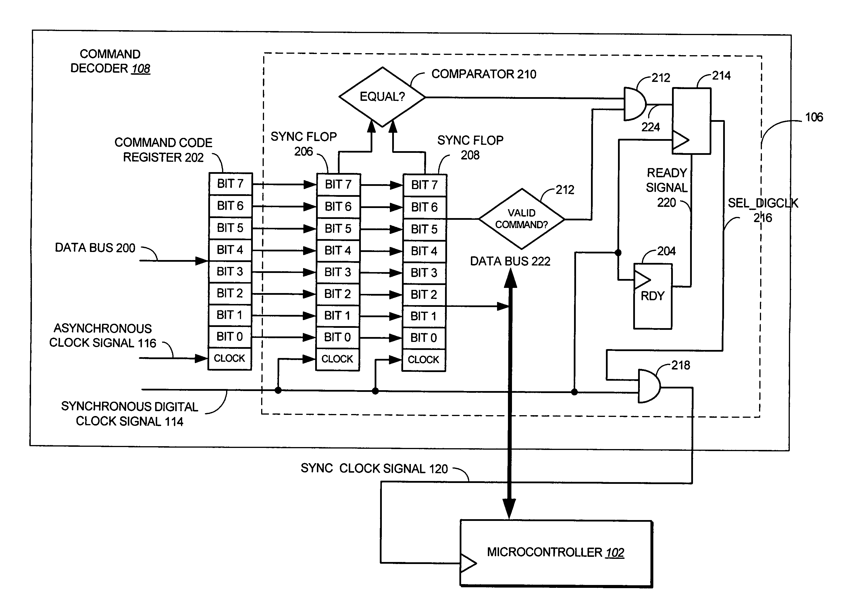
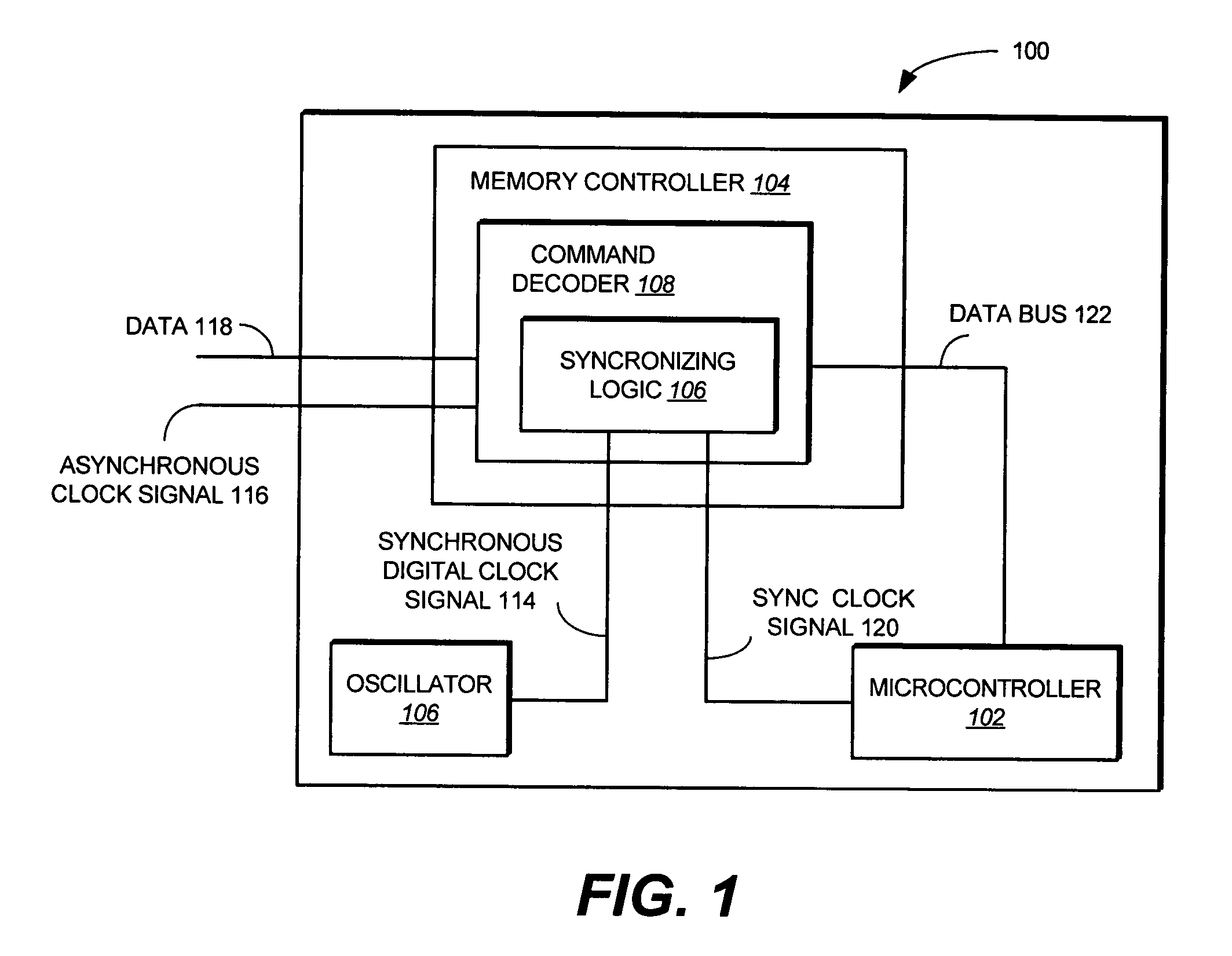
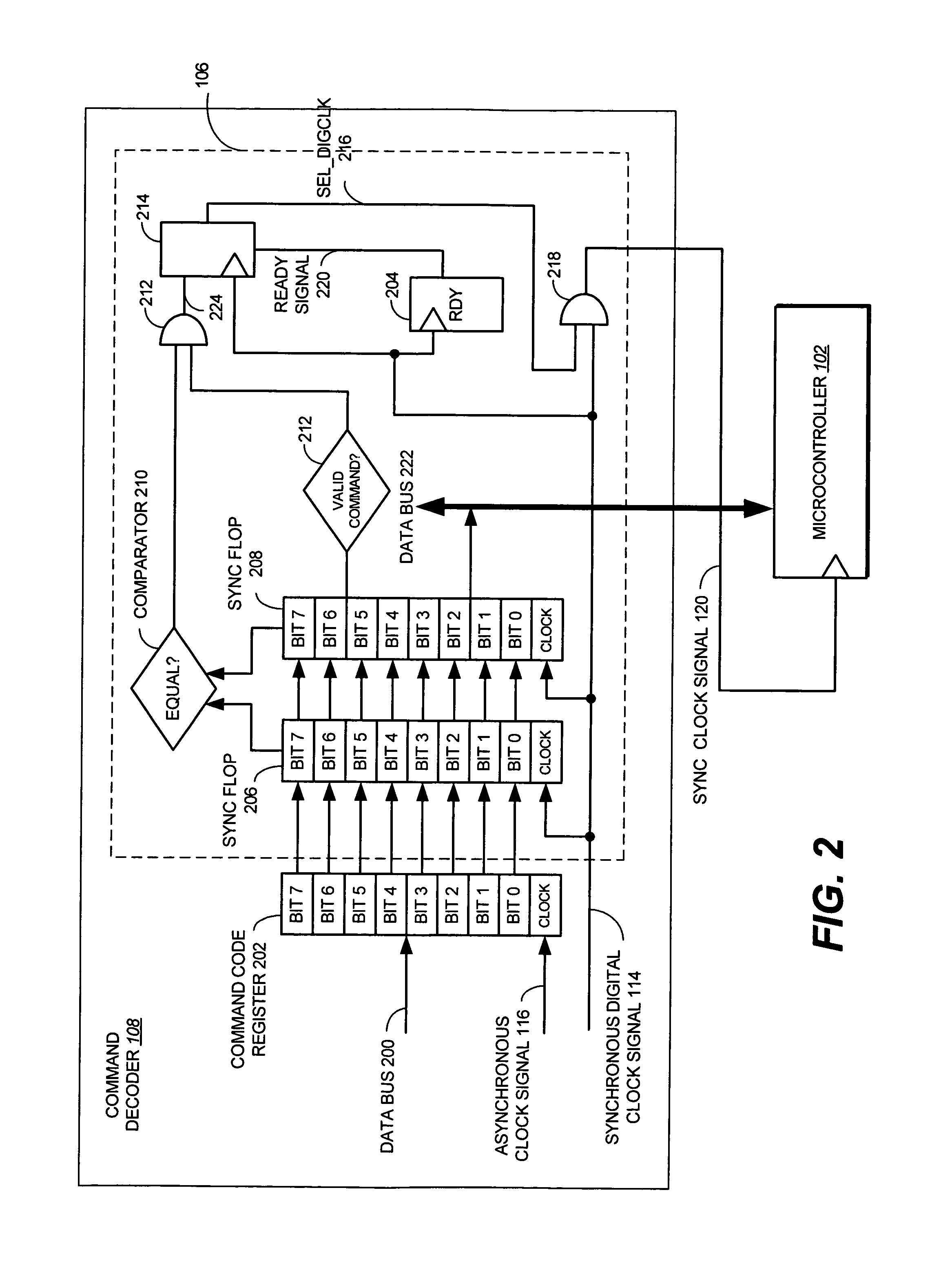
[0018]FIG. 1 is a block diagram illustrating a system 100 according to one embodiment of the invention. The system 100 includes a microcontroller 102, a memory controller 104, and an oscillator 106.

[0019]The microcontroller 102 is coupled to the memory controller 104. The memory controller 104 can be any type of digital...


PUM


Abstract

The present invention provides method and apparatus for synchronizing data between different clock domains in a memory controller. In one embodiment, a memory controller is provided that includes a command decoder and synchronizing logic. The command decoder is operable to receive a command in accordance with a first clock domain. The synchronizing logic synchronizes the command to a second clock domain that is different from the first clock domain, and includes a first synchronization flop and a second synchronization flop operable to prevent metastability associated with synchronizing the command to the second clock domain.

Description

FIELD OF THE INVENTION[0001]The present invention relates to electrical circuits, and more particularly to synchronization and sleep circuits in a memory controller.BACKGROUND OF THE INVENTION[0002]Modern electronic systems typically contain many components including, for example, processors (or microcontrollers), main boards, memories, storage, graphics processors, and the like. One goal of manufacturers is to improve performance by increasing the speed at which an electronic system operates. Consequently, processor speed has increased steadily over the years.[0003]Performance improvements of the various components in electronic systems, however, have not all been related to speed improvements. As a result, certain parts of an electronic system may run at different speeds (or clock frequencies) relative to one another. For example, a user interface of an electronic system (for receiving user commands) may be asynchronous (i.e., operating at a different clock frequency or an indepen...

Claims


Application Information

Patent Timeline
Patent Type & Authority Patents(United States)
IPC IPC(8): H04L7/00H04L7/02
CPCG06F13/1689Y02B60/1228Y02D10/00
Inventor COHEN, DANIEL SCOTT
Owner ATMEL CORP
Why Eureka
Try Eureka