Cooling apparatus and method for controlling the same

a technology of cooling apparatus and control method, which is applied in the direction of electrical apparatus casings/cabinets/drawers, ventilation systems, heating types, etc., can solve the problems of system overcooling, unnecessarily excessive power consumption and excessive noise, and the use of expensive pressure meters for altimeters, so as to effectively cool the heat source and minimize the generation of noise. , the effect of effective cooling

Inactive Publication Date: 2010-01-05
LG ELECTRONICS INC
View PDF15 Cites 21 Cited by
  • Summary
  • Abstract
  • Description
  • Claims
  • Application Information

AI Technical Summary

Benefits of technology

[0022]An object of the present invention is to provide a cooling apparatus and a method for controlling the same which are capable of effectively cooling a heat source in accordance with an altitude of the heat source measured based on the temperature difference between air supplied to cool the heat source and air discharged after being used to cool the heat source.
[0023]Another object of the present invention is to provide a cooling apparatus and a method for controlling the same which are capable of effectively cooling a heat source while minimizing generation of noise by a cooling fan used to cool the heat source.
[0024]Still another object of the present invention is to provide a cooling apparatus and a method for controlling the same which are capable of stepwise increasing or decreasing the rotating speed of a cooling fan used to cool a heat source, and thus, maximizing the comfort of the user expected in accordance with low-noise driving of the cooling fan.

Problems solved by technology

However, when the cooler design is made on the basis of an area of a high altitude, there is a possibility that system overcooling may occur in areas where the density of air is high.
In such areas, there are additional problems of unnecessarily excessive power consumption and excessive noise.
In most conventional systems, expensive pressure meters are used for altimeters.
For this reason, there is a problem in that an increase in system manufacturing costs occurs.
However, these methods have a problem in that they are unsuitable for notebook computers which are conveniently usable by virtue of their mobility and portability.

Method used


Image

  • Cooling apparatus and method for controlling the same
  • Cooling apparatus and method for controlling the same
  • Cooling apparatus and method for controlling the same

Examples


first embodiment

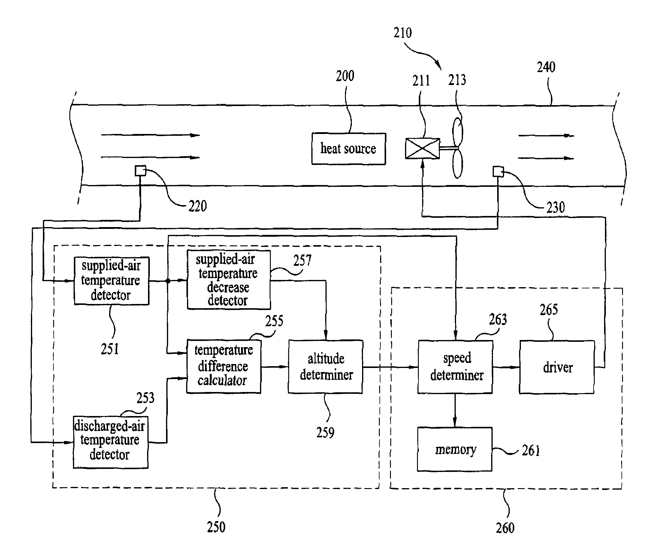
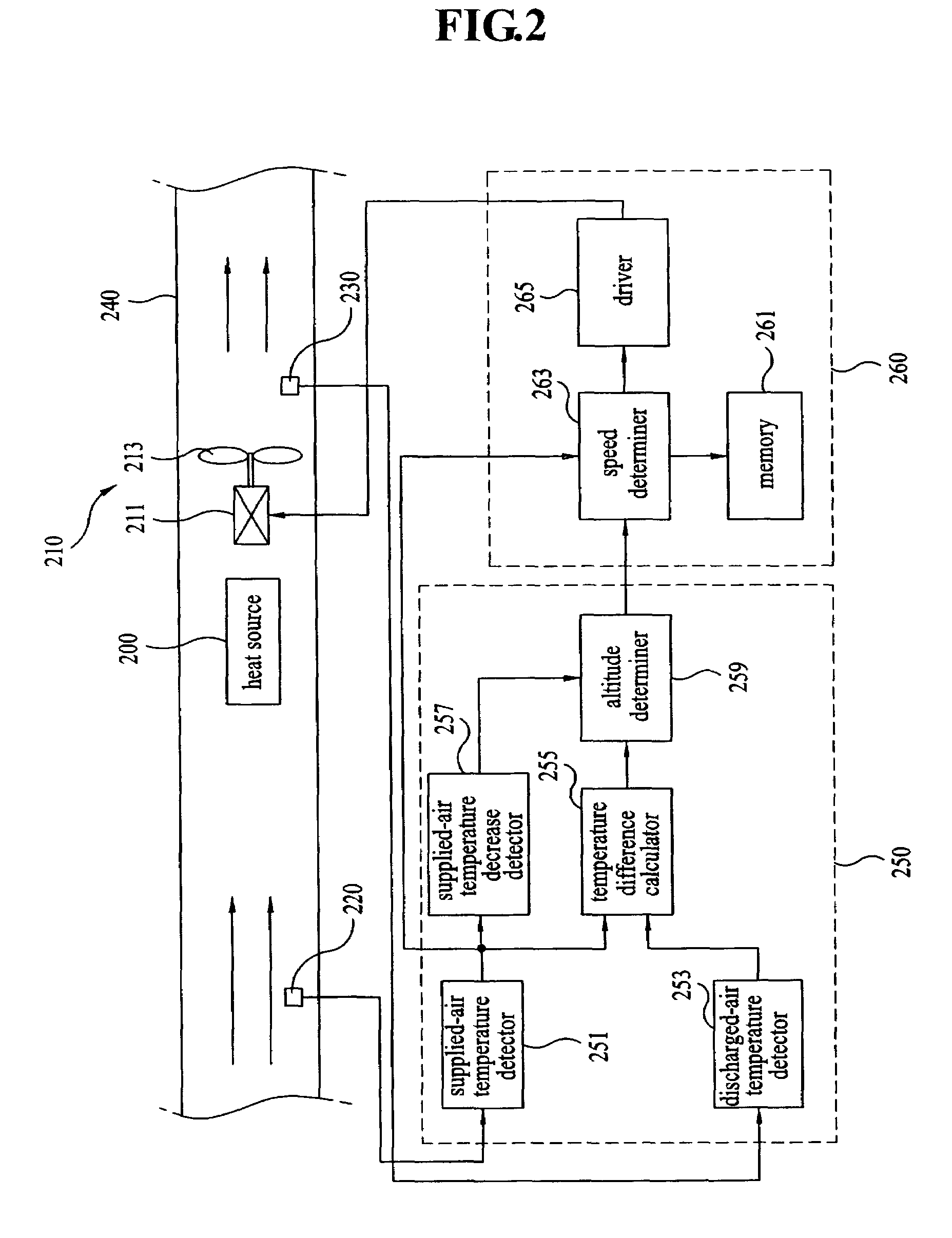
[0053]FIG. 2 is a schematic diagram illustrating a configuration of the cooling apparatus according to the present invention.

[0054]In FIG. 2, reference numeral “200” designates a heat source which generates heat, such as a light source internally arranged in a system such as a projector or a projection type television receiver. Reference numeral “210” designates an air stream forming unit which forms an air stream to cool the heat source.

[0055]The air stream forming unit 210 includes a fan motor 211, and a cooling fan 213 which causes air to pass around the heat source 200 while rotating in accordance with a driving operation of the fan motor 211, thereby cooling the heat source 200.

[0056]Reference numeral “220” designates a supplied-air temperature sensor which measures the temperature of air supplied to the heat source 200. Reference numeral “230” designates a discharged-air temperature sensor which measures the temperature of air discharged after cooling the heat source 200.

[0057...

second embodiment

[0078]FIG. 3 is a schematic diagram illustrating a configuration of the cooling apparatus according to the present invention.

[0079]The second embodiment of the present invention is different from the first embodiment of the present invention in terms of the arrangement of the air stream forming unit 210. As shown in FIG. 3, the air stream forming unit 210 may be arranged between the supplied-air temperature sensor 220 and the heat source 200, differently from the first embodiment of the present invention in which the air stream forming unit 210 is arranged between the heat source 200 and the discharged-air temperature sensor 230. In this case, similarly to the first embodiment of the present invention, it is possible to detect the altitude of the system and the temperature of the supplied air, to determine the rotating speed of the fan motor 211, based on the detected altitude and the detected supplied-air temperature, and to rotate the fan motor 211 based on the determined rotating...


PUM


Abstract

A cooling apparatus and a method for controlling the same are disclosed. The cooling apparatus is adapted to cool a system in which a heat source generating heat is arranged. The cooling apparatus includes an air stream forming unit which cools the heat source to a certain temperature, a sensing unit which includes a supplied-air temperature sensor for sensing a temperature of air supplied into the system, and a discharged-air temperature sensor for sensing a temperature of air discharged out of the system, an altitude detecting unit which detects an altitude of the system, based on the sensed supplied-air temperature and the sensed discharged-air temperature, and a cooling controller which controls the air stream forming unit, based on the detected altitude.

Description

[0001]This application claims the benefit of Korean Patent Application No. 10-2005-0026309, filed on Mar. 30, 2005 and No. 10-2005-0026321, filed on Mar. 30, 2005, which is hereby incorporated by reference as if fully set forth herein.BACKGROUND OF THE INVENTION[0002]1. Field of the Invention[0003]The present invention relates to a cooling apparatus, and more particularly, to a cooling apparatus for a system including a heat source, and a method for controlling the cooling apparatus.[0004]2. Discussion of the Related Art[0005]A variety of systems such as computers, projectors, and projection type television receivers inevitably have heat sources. Heat generated from such a heat source should be effectively dissipated, in order to enable the associated system to operate normally, and to prevent elements arranged around the heat source from being damaged due to the heat.[0006]In order to dissipate heat generated from a heat source, namely, to cool the heat source, a forced convection ...

Claims


Application Information

Patent Timeline
Patent Type & Authority Patents(United States)
IPC IPC(8): F24F11/00F24F7/007G03B21/16H05K5/00
CPCG06F1/206G05D23/20G05D23/1931
Inventor BOK, KI SOLIM, HYUNG JINKIM, DAE WOO
Owner LG ELECTRONICS INC
Why Eureka
Try Eureka