Fast automatic linear off-resonance correction method for spiral imaging

a spiral imaging and off-resonance correction technology, applied in the field of correction of offresonance in magnetic resonance imaging, can solve problems such as image blurring in spiral imaging, and achieve the effects of increasing estimation error, robustness, and increasing the extent of correction

Active Publication Date: 2010-01-05
UNIV OF VIRGINIA ALUMNI PATENTS FOUND
View PDF10 Cites 18 Cited by
  • Summary
  • Abstract
  • Description
  • Claims
  • Application Information

AI Technical Summary

Benefits of technology

[0028]Our method is more robust than the pixel-by-pixel based automatic off-resonance correction methods in regions with low SNR. It can also be combined with Noll et al.'s (11) automatic method to increase the extent of correction without increasing estimation error.
[0029]Field inhomogeneity and susceptibility variations, coupled with a long readout, can result in image blurring in spiral imaging. Many correction methods based on a priori off-resonance information, such as an acquired field map, have been proposed in the literature. Automatic off-resonance correction methods are alternative approaches that estimate a field map from the image data themselves. The present invention provides a fast automatic off-resonance correction method that performs linear correction without acquiring a field map. The method requires only about two times the total computation time compared to image reconstruction by gridding. It can also be used in combination with a full field map automatic off-resonance correction method to increase the extent of correction. The method is demonstrated by in vivo coronary artery imaging.

Problems solved by technology

Field inhomogeneity and susceptibility variations, coupled with a long readout, can result in image blurring in spiral imaging.

Method used


Image

  • Fast automatic linear off-resonance correction method for spiral imaging
  • Fast automatic linear off-resonance correction method for spiral imaging
  • Fast automatic linear off-resonance correction method for spiral imaging

Examples


Embodiment Construction

[0037]A preferred embodiment of the present invention will be set forth in detail with reference to the drawings, in which like reference numerals refer to like elements or steps throughout.

[0038]Linear off-resonance correction is accomplished in the following manner. The MR signal, ignoring relaxation, from an object with spin density m(x,y) is given by

s(t)=∫∫m(x,y)exp(−i2π(kx(t)x+ky(t)y+f(x,y)t))dxdy  (1)

[0039]where kx(t) and ky(t) are the x and y components of the k-space trajectory, respectively, and f(x,y) is the spatial distribution of the resonant frequency.

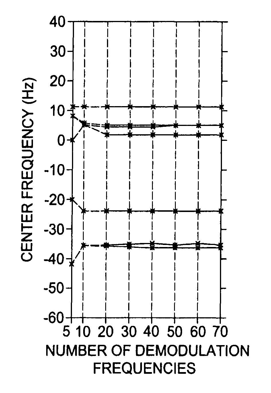
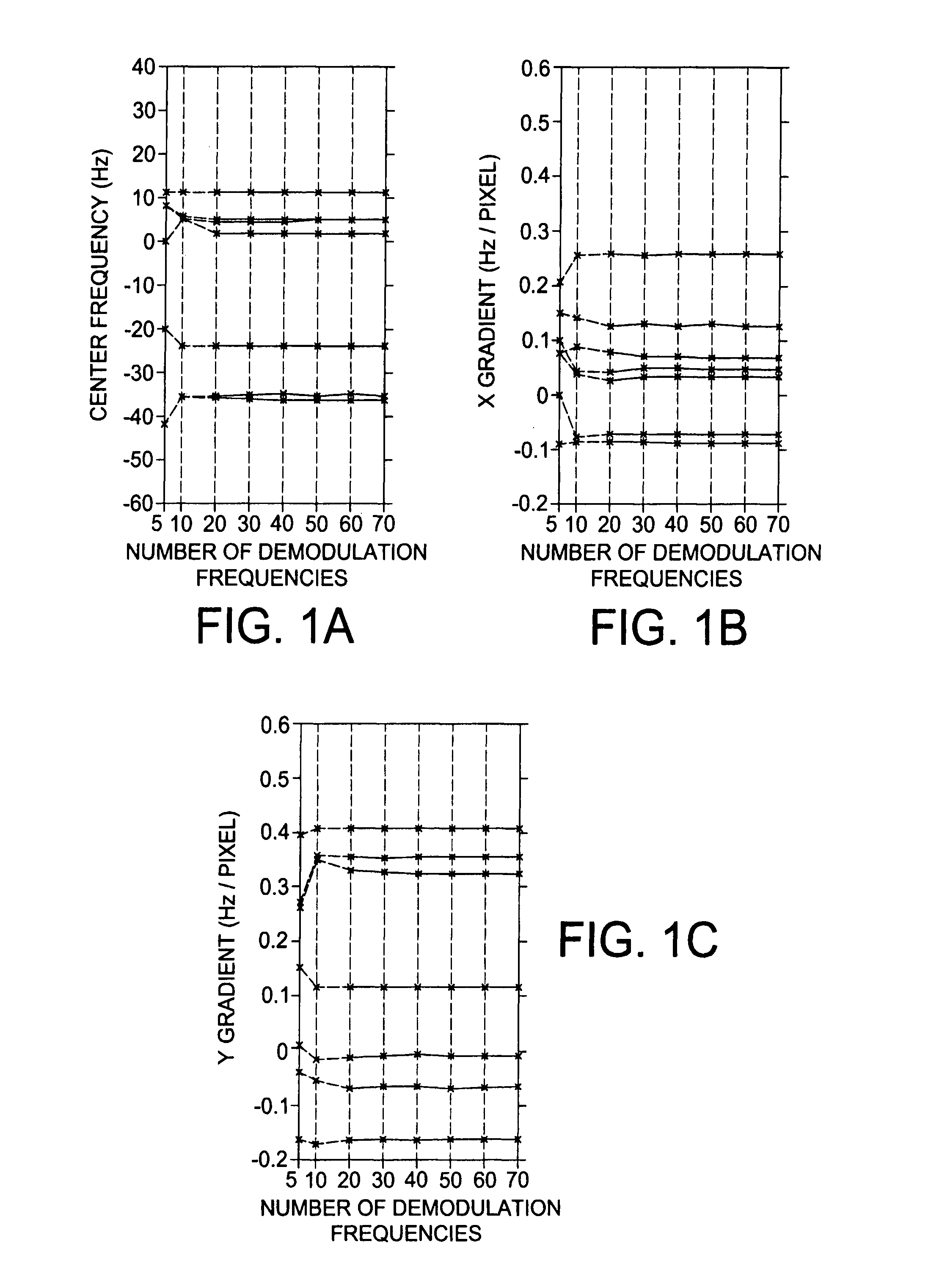
[0040]Assume there is only one linear field variation, namely,

f(x,y)=f0+αx+βy  (2)

[0041]where f0 is the center frequency and α and β are the x and y gradients of the linear map, respectively. The signal equation can be rewritten as

s′(t)=∫∫m(x,y)exp(−i2π(kx′(t)x+ky′(t)y))dxdy  (3)

[0042]with

[0043]s′(t)≡s(t)·exp(i2πf0t)

[0044]kx′(t)≡kx(t)+αt

[0045]ky′(t)≡ky(t)+βt

[0046]The image can be reconstructed from the signal by gridding (...


PUM


Abstract

A fast automatic linear off-resonance correction method for MRI data uses a set of widely spaced demodulation frequencies to estimate a low-resolution field map from the image itself. A linear map is determined by fitting to this low-resolution map using a maximum-likelihood estimator with weights proportional to the pixel intensity.

Description

REFERENCE TO RELATED APPLICATION[0001]The present application claims the benefit of U.S. Provisional Patent Application No. 60 / 839,037, filed Aug. 21, 2006, whose disclosure is hereby incorporated by reference in its entirety into the present disclosure.FIELD OF THE INVENTION[0002]The present invention is directed to the correction of off-resonance in magnetic resonance imaging and more particularly to such correction with improved speed.DESCRIPTION OF RELATED ART[0003]Off-resonance commonly exists in MRI. The chemical shift between fat and water is one main source of off-resonance, which can be suppressed by a spectral-spatial pulse (I) or fat presaturation technique. Other sources of off-resonance are the main field inhomogeneity and tissue-induced susceptibility changes. Off-resonance causes only image misregistration of pixels for 2DFT data acquisition, which is usually not a serious problem. However, for non-2DFT data acquisitions, such as projection reconstruction and spiral i...

Claims


Application Information

Patent Timeline
Patent Type & Authority Patents(United States)
IPC IPC(8): G01V3/00
CPCG01R33/56563G01R33/4824G01R33/5601G01R33/561G01R33/56536
Inventor MEYER, CRAIG H.CHEN, WEITIAN
Owner UNIV OF VIRGINIA ALUMNI PATENTS FOUND
Why Eureka
Try Eureka