
Sensor apparatus

a sensor and circuit technology, applied in the direction of instruments, pedestrian/occupant safety arrangements, vehicular safety arrangements, etc., can solve the problems of sensor apparatus not being able to sensor apparatus may be increased in size and cost, sensor apparatus can not detect a large physical quantity, etc., to achieve the effect of ensuring high sensitivity, ensuring high sensitivity, and greatly increasing the dynamic range of the sensor circui

Inactive Publication Date: 2010-01-05
DENSO CORP
View PDF9 Cites 13 Cited by
  • Summary
  • Abstract
  • Description
  • Claims
  • Application Information

AI Technical Summary

Benefits of technology

[0006]In view of the above-described problem, it is an object of the present invention to provide a sensor apparatus having a wide dynamic range and a high sensitivity.
[0008]According to the sensor apparatus, the detection signal is used after being converted to the logarithm signal. As the detection signal is smaller, the logarithm signal is larger. As the detection signal is larger, the logarithm signal is smaller. Therefore, the dynamic range of the sensor circuit is greatly increased by using the logarithm signal. The detection signal is digitalized after being converted to the logarithm signal. In such an approach, even when the detection signal is small, the detection signal can be digitalized at high resolution so that high sensitivity can be ensured. Further, even when the detection signal is large, the detection signal can be digitalized without signal distortion so that high sensitivity can be ensured.

Problems solved by technology

In such a conventional sensor apparatus, an increase in a sensitivity of the sensor circuit results in a decrease in a dynamic range of the sensor circuit, because an output of the sensing circuit is limited to a power supply voltage.
Therefore, if the sensitivity of the sensor circuit is increased to detect a small physical quantity, the sensor apparatus cannot detect a large physical quantity due to a small dynamic range.
However, this approach requires multiple sensor circuits and multiple processing circuits for processing outputs of the respective sensor circuits.
As a result, the sensor apparatus may be increased in size and cost.

Method used


Image

  • Sensor apparatus
  • Sensor apparatus
  • Sensor apparatus

Examples


Embodiment Construction

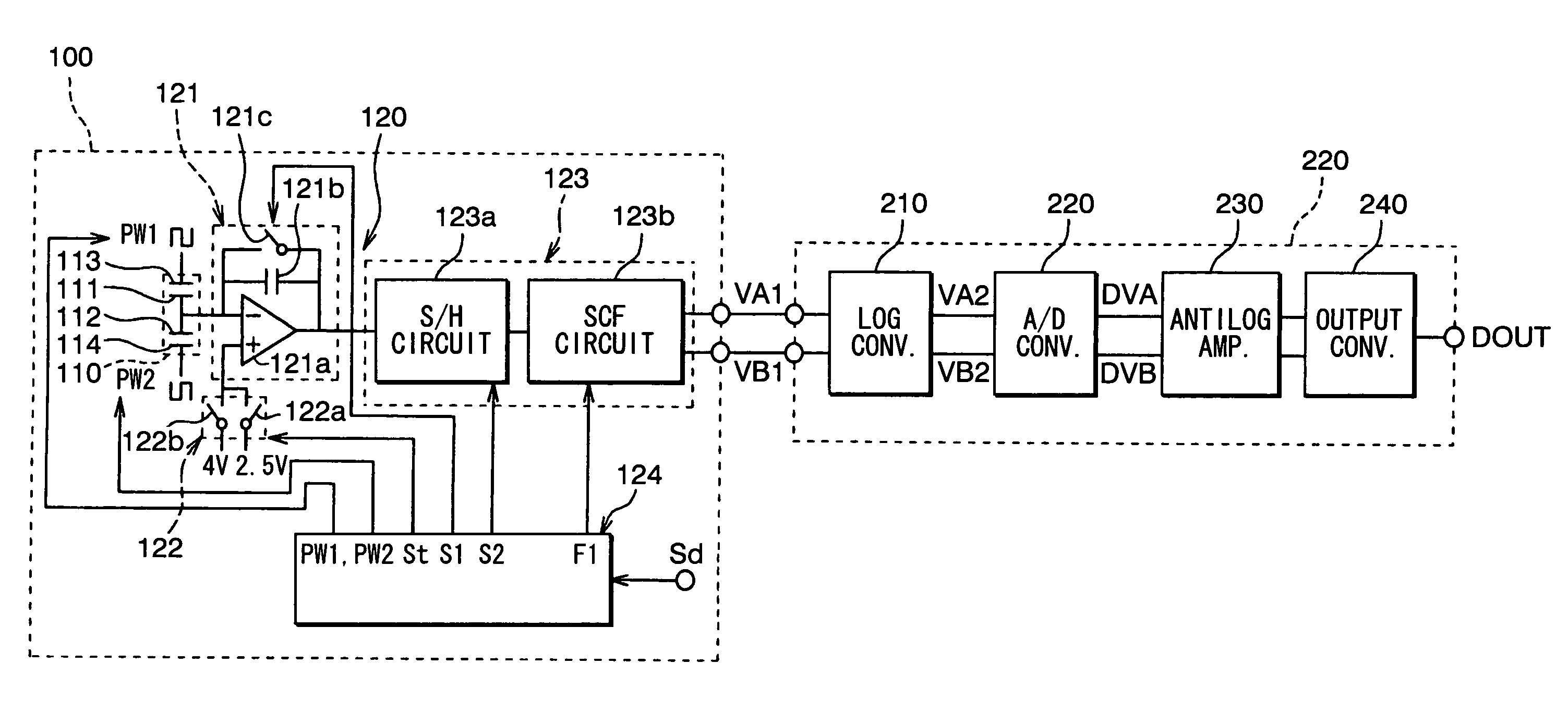
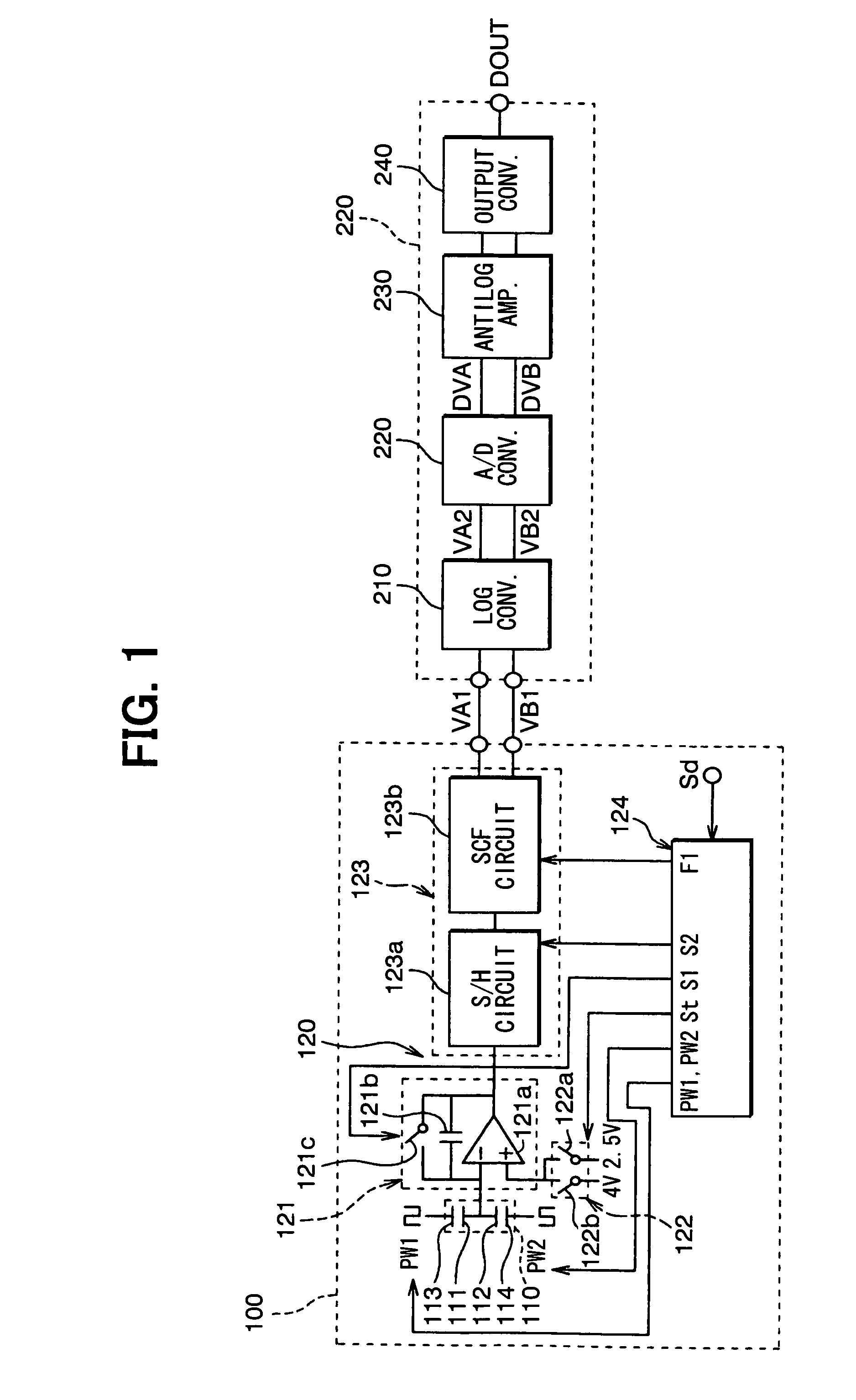
[0015]Referring to FIG. 1, a sensor apparatus according to an embodiment of the present invention includes a sensor circuit 100 and a nonlinear signal processing circuit 200. For example, the sensor apparatus can be installed in a vehicle to achieve a vehicle control such as an airbag control or a sideslip prevention.

[0016]The sensor circuit 100 detects a physical quantity. In the present embodiment, the sensor circuit 100 is configured as an acceleration sensor to detect acceleration. The sensor circuit 100 includes a sensor element 110 and a detection circuit 120.

[0017]The sensor element 110 includes a comb-shaped beam structure formed on a silicon substrate. The comb-shaped beam structure is constructed with movable electrodes 111, 112, and fixed electrodes 113, 114. The movable electrode 111 and the fixed electrode 113 are arranged opposite to each other, and the movable electrode 112 and the fixed electrode 114 are arranged opposite to each other. Thus, the sensor element 110 h...


PUM


Abstract

A sensor apparatus includes a sensor circuit and a nonlinear signal processing circuit. The sensor circuit detects a physical quantity and outputs a detection signal indicative of the detected physical quantity. The signal processing circuit includes a logarithmic converter, an analog-to-digital converter, and an antilogarithmic converter. The logarithmic converter produces a logarithm signal corresponding to a logarithm of the detection signal. The analog-to-digital converter digitalizes the logarithm signal. The antilogarithmic converter produces an antilogarithmic signal corresponding to an antilogarithm of the digitalized logarithm signal.

Description

CROSS REFERENCE TO RELATED APPLICATION[0001]This application is based on and incorporates herein by reference Japanese Patent Application No. 2006-332893 filed on Dec. 11, 2006.FIELD OF THE INVENTION[0002]The present invention relates to a sensor apparatus having a wide dynamic range and a high sensitivity.BACKGROUND OF THE INVENTION[0003]A sensor apparatus has been proposed that detects acceleration as a physical quantity. For example, a sensor apparatus disclosed in U.S. Pat. No. 6,483,322 corresponding to JP-A-200240047 includes a sensor circuit and a processing circuit. The sensor circuit detects a capacitance varying with acceleration applied thereto and outputs an acceleration signal indicative of the detected capacitance. The processing circuit processes the acceleration signal. The processing circuit has a function to convert the acceleration signal to a voltage signal and to linearly amplify the voltage signal.[0004]When a physical quantity to be detected is small, a sensit...

Claims


Application Information

Patent Timeline
Patent Type & Authority Patents(United States)
IPC IPC(8): G08B21/00
CPCB60R21/0132G01P15/08G01P15/125
Inventor HAYAKAWA, JUNJI
Owner DENSO CORP
Learn More