Rotationally tunable optical delay line

Inactive Publication Date: 2010-01-05
SOKOLOFF JASON P +1
View PDF6 Cites 8 Cited by
  • Summary
  • Abstract
  • Description
  • Claims
  • Application Information

AI Technical Summary

Benefits of technology

[0009]Therefore, it is desirable to have a new device for generating time delays in autocorrelators or pulsed laser devices, which can overcome the drawbacks o

Problems solved by technology

Most, if not all of these approaches require multiple mechanical components which take up significant space and require careful optical alignment that is difficult to maintain over time.
A drawback of this approach is that large changes in the angle of incidence 13, that is large swing angles, are necessary to achieve time delays commonly used in autocorrelators.
Another drawback of this approach, as can be seen in FIG. 3, is that the delay of one beam relative to the other never crosses through zero.
A further drawback of this approach is that the mechanical drive that repeatedly scans the Wan Time Plate must be of a reciprocating nature or at the very least an indirect drive mechanism which requires some complex coupling or control.

Method used


Image

  • Rotationally tunable optical delay line
  • Rotationally tunable optical delay line
  • Rotationally tunable optical delay line

Examples


case 1

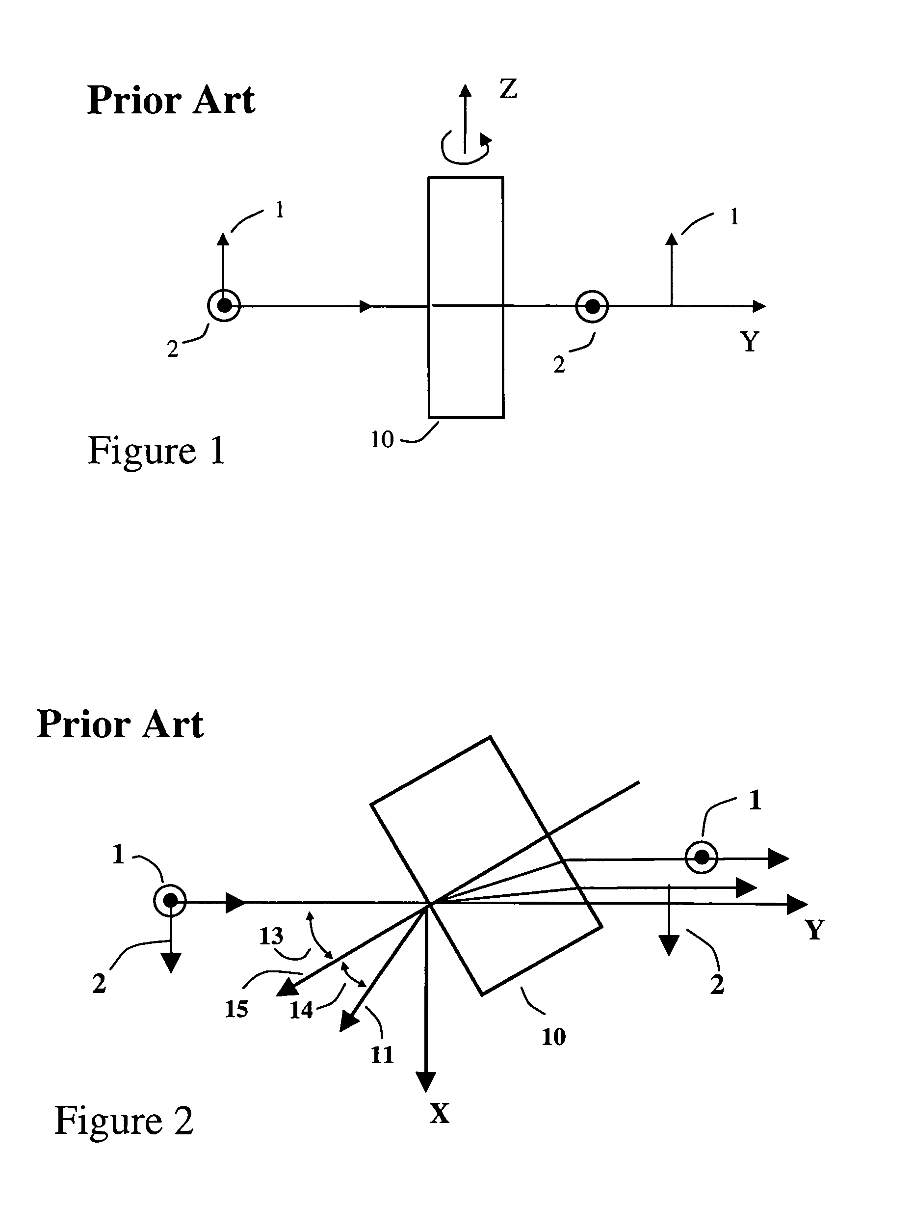
[0076]The light ray enters traveling parallel to the c-axis. In this case the light ray is polarized perpendicular to the c-axis and is called an ordinary ray or “o-ray”. Its propagation velocity depends only on the value of the crystal's ordinary refractive index, no.

case 2

[0077]The light ray enters traveling perpendicular to the c-axis. In this case any component of the light ray that is polarized perpendicular to the c-axis is an o-ray, but any component of the light that is polarized parallel to the c-axis is called an extraordinary ray or “e-ray”. The propagation velocity of the e-ray is different from that of the o-ray and depends only on the value of the crystal's extra-ordinary refractive index, ne.

case 3

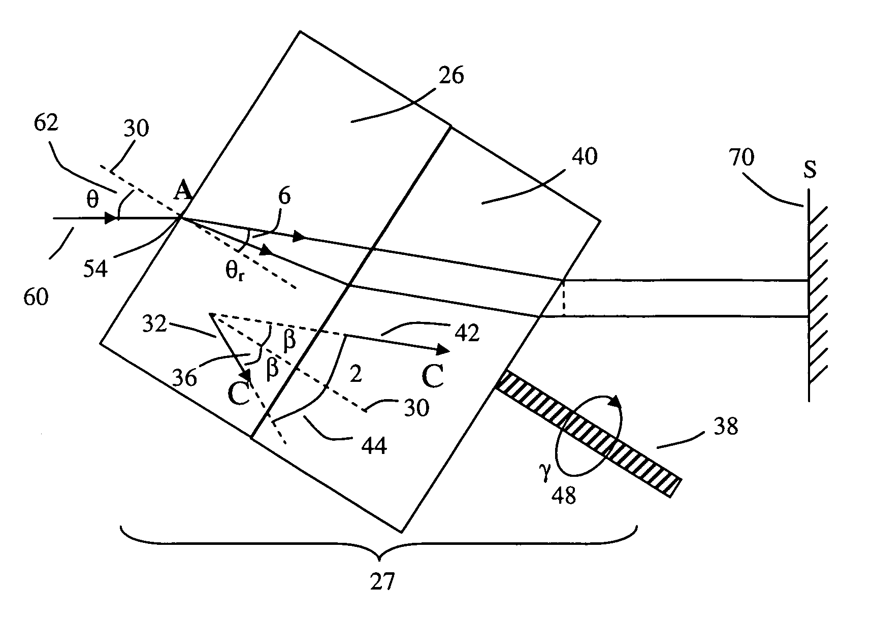
[0078]The light ray enters the uniaxial crystal along a direction not parallel to the crystal c-axis. It separates into two orthogonally polarized rays: an ordinary ray or “o-ray”, and an extraordinary ray or “e-ray”. These two rays travel at slightly different velocities and in slightly different directions. The o-ray is polarized perpendicular to the c-axis and propagates at a speed dependent on the crystal's ordinary refractive index, no. The e-ray is polarized in the plane defined by the o-ray and c-axis, and propagates at a speed that depends on no, ne, and φ—the angle between the o-ray and the c-axis. For this general case the e-ray refractive index has an angular dependence

ne(φ)=[sin2(φ) / ne2+cos2(φ) / no2]−1 / 2  (1)

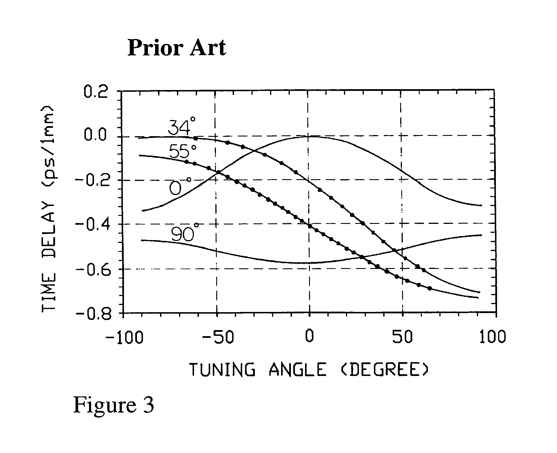
When φ=0 degrees, case 3 reduces to case 1. When φ=90 degrees, case 3 reduces to case 2. Since the e-ray propagation velocity depends on ne,(φ), then equation (1) shows that the e-ray transit time through a uniaxial crystal can be changed by adjusting φ. This property...


PUM


Abstract

A rotationally tunable time delay line device for providing a continually adjustable time delay between two orthogonally polarized laser pulses is described. The device is comprised of one or more rotational delay crystals, each made of a flat uniaxially birefringent crystal with a special orientation of its internal optical axis. The time delay generated between the two orthogonally polarized laser pulses that travel through the rotationally tunable delay line can be continually adjusted by rotating the constituent rotational delay crystals around their surface normals. An application is demonstrated in detail where the rotationally tunable time delay line device is used to form an optical autocorrelator for measuring femtosecond or picosecond duration laser pulses.

Description

CROSS REFERENCE TO RELATED APPLICATIONS [0001]This application claims priority from Provisional Patent Application No. 60 / 998,374 filed Oct. 10, 2007 by the present inventors, which is incorporated by reference.FEDERALLY SPONSORED RESEARCH[0002]NoneSEQUENCE LISTING[0003]NoneFIELD OF INVENTION[0004]The present invention relates to tunable optical delay lines, specifically tunable optical delay lines that have applications in optical communications systems as well as in optical test and measurement devices, including a device known as an optical autocorrelator which is commonly used for measuring the duration of ultrashort optical pulses.DISCUSSION OF PRIOR ART[0005]Tunable optical delay lines are used to control the transit time of a light beam between two points. Conventionally a delay line device has been utilized in many applications including compensating time delay in pulsed laser devices, and scanning the delay of one pulse relative to another in ultrafast spectroscopy or optic...

Claims


Application Information

Patent Timeline
IPC IPC(8): G01B9/02G02B5/30
CPCG02B26/0883
Inventor SOKOLOFF, JASON P.SOKOLOFF, LAWRENCE
Owner SOKOLOFF JASON P
Why Eureka
Try Eureka