Method and apparatus for synchronizing clock timing between network elements

a technology of network elements and clock timing, applied in multiplex communication, generating/distributing signals, instruments, etc., can solve problems such as difficult synchronization of different tdm networks and network elements on these tdm networks, period line errors, and increased jitter and delay in transmission

Active Publication Date: 2010-01-05
CIENA
View PDF15 Cites 29 Cited by
  • Summary
  • Abstract
  • Description
  • Claims
  • Application Information

AI Technical Summary

Benefits of technology

[0015]According to another embodiment of the invention, to ensure that the local oscillators in the slave DCFSs are oscillating at the same frequency as the master local oscillator, the slave local oscillators are formed as voltage controlled oscillators and a feedback loop is used to synchronize the slave local oscillators with the master local oscillator. In one embodiment, time stamps are used to transmit state information from the master local oscillator to the slave local oscillators so that the slave local oscillators may replicate the frequency of the master local oscillator to eliminate any long term drift of the slave local oscillator relative to the master local oscillator.

Problems solved by technology

If the physical interfaces on a connection are not synchronized (not driven by a clocking signal of identical frequency), data can be lost due to buffer overflow or underflow, resulting in periodic line errors.
The non-synchronous nature of the packet network and the packetizing and depacketizing processes used to format the data for transmission over the packet network all contribute to increased jitter and delay in the transmission of traffic, which makes synchronization of the different TDM networks and network elements on these TDM networks difficult.
Additionally, while packet networks are able to carry traffic between the end TDM networks, they do not naturally carry clock information due to their asynchronous nature.

Method used


Image

  • Method and apparatus for synchronizing clock timing between network elements
  • Method and apparatus for synchronizing clock timing between network elements
  • Method and apparatus for synchronizing clock timing between network elements

Examples


Embodiment Construction

[0040]The following detailed description sets forth numerous specific details to provide a thorough understanding of the invention. However, those skilled in the art will appreciate that the invention may be practiced without these specific details. In other instances, well-known methods, procedures, components, protocols, algorithms, and circuits have not been described in detail so as not to obscure the invention.

First Level Control—Exchange of Control Words

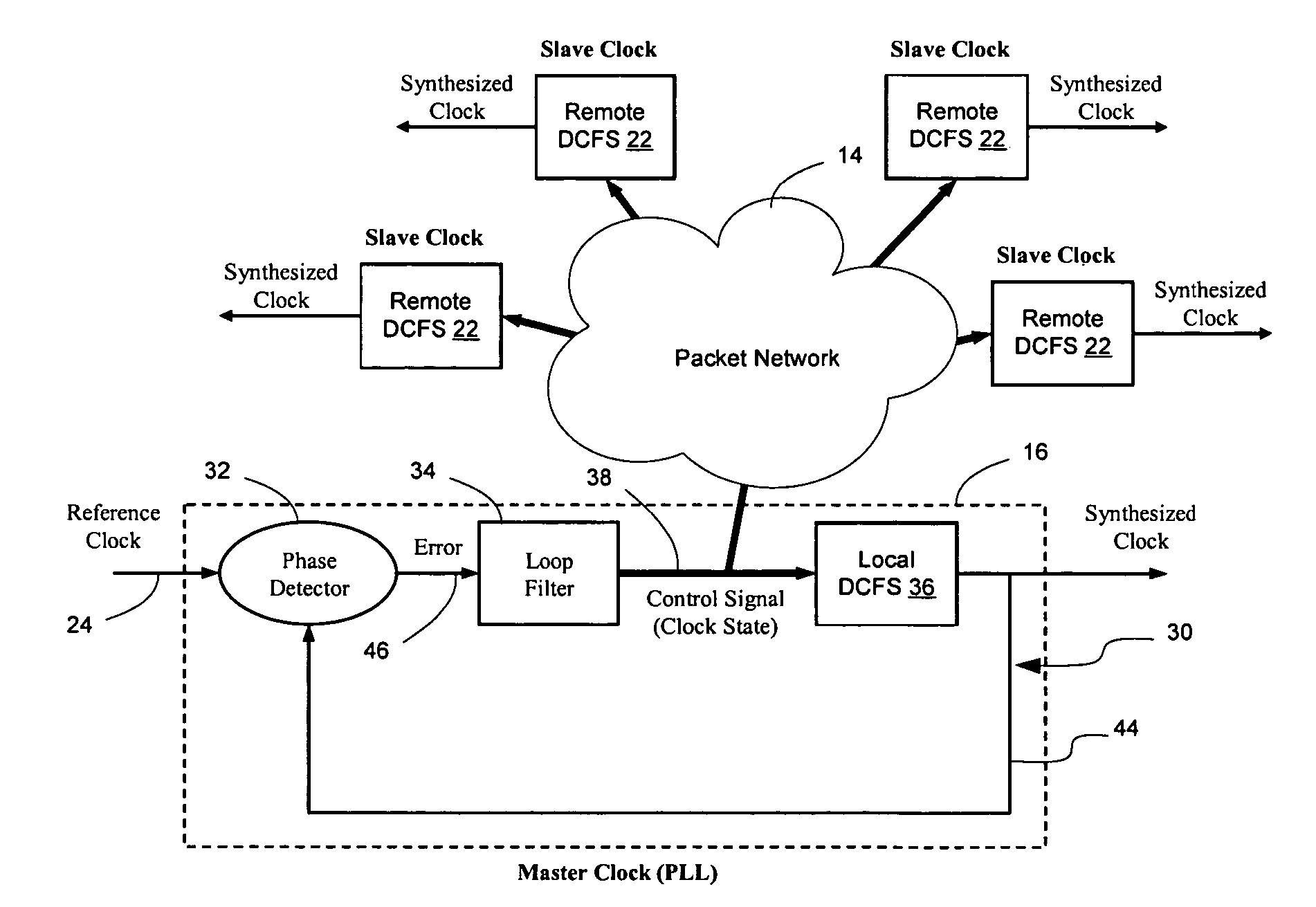
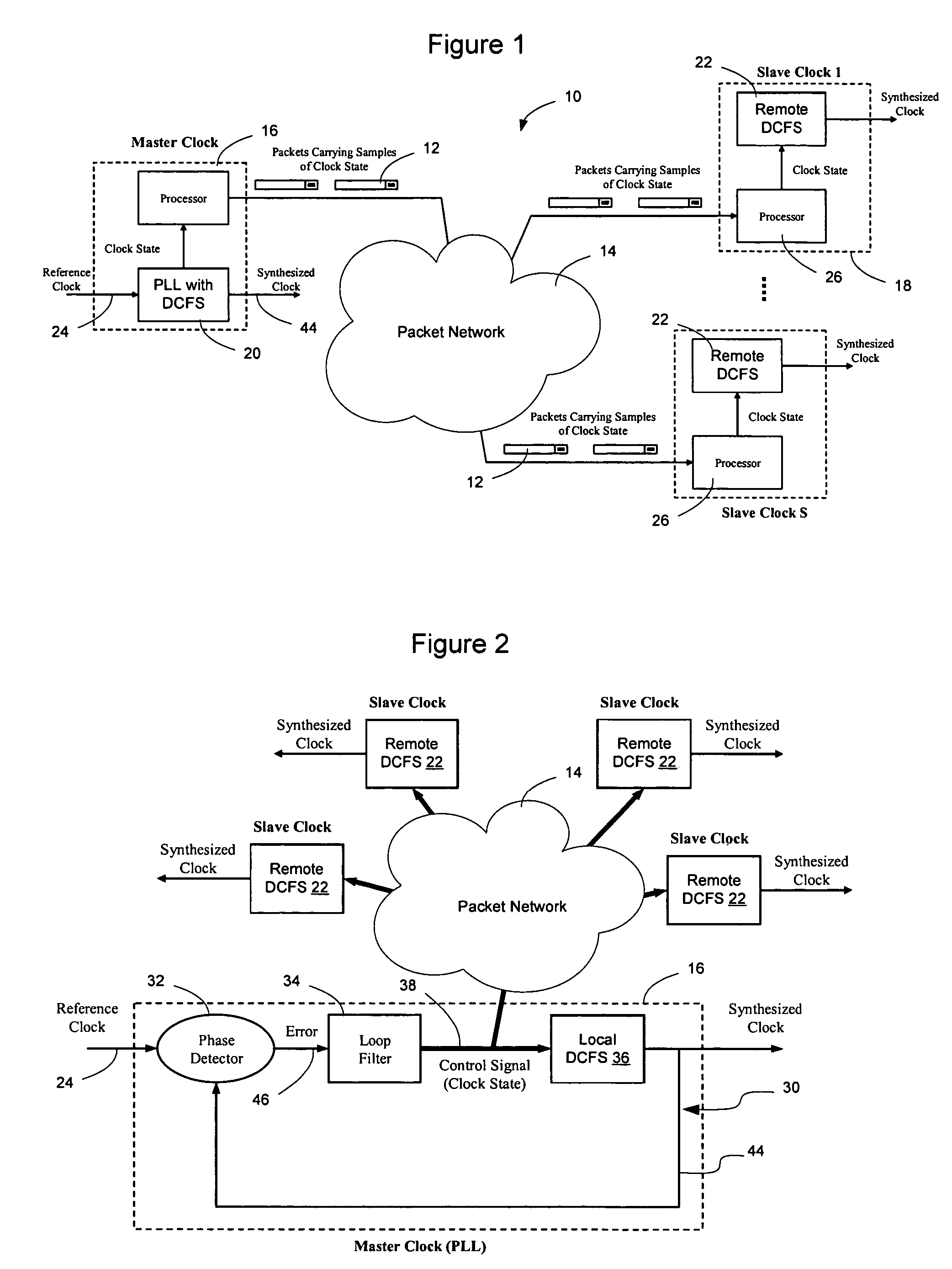
[0041]FIG. 1 illustrates an example network 10 in which clock information 12 is carried across a packet network 14 from a master clock 16 to one or more slave clocks 18. As shown in FIG. 1, synchronization of the master and slave clocks is achieved over a packet (non TDM) portion of the network 10 by transmitting packets 12 containing clock state information from the master clock 16 to the slave clocks 18. The master clock 16, according to embodiments of the invention, includes an all digital phase locked loop including a Digit...


PUM


Abstract

Network elements may be synchronized over an asynchronous network by implementing a master clock as an all digital PLL that includes a Digitally Controlled Frequency Selector (DCFS), the output frequency of which may be directly controlled through the input of a control word. The PLL causes the control word input to the master DCFS to be adjusted to cause the output of the master DCFS to lock onto a reference frequency. Information associated with the control word is transmitted from the master clock to the slave clocks which are also implemented as DCFSs. By using the transmitted information to recreate the master control word, the slaves may be made to assume the same state as the master DCFS without requiring the slaves to be implemented as PLLs. The DCFS may be formed as a digitally controlled oscillator (DCO) or as a Direct Digital Synthesizer (DDS).

Description

CROSS REFERENCE TO RELATED APPLICATIONS[0001]This application is related to and claims the benefit of U.S. Provisional Application No. 60 / 609,477, filed Sep. 13, 2004; U.S. Provisional Application No. 60 / 609,478, filed Sep. 13, 2004; U.S. Provisional application No. 60 / 630,550, filed Nov. 23, 2004; and U.S. Provisional Application No. 60 / 674,231, filed Apr. 23, 2004, and is also related to U.S. Patent Application entitled Method And Apparatus For Synchronizing Internal State of Frequency Generators On A Communications Network, filed on even date herewith. The content of each of these provisional and utility applications is hereby incorporated herein by reference.BACKGROUND OF THE INVENTION[0002]1. Field of the Invention[0003]The present invention relates to communication networks and, more particularly, to a method and apparatus for synchronizing clock timing between network elements.[0004]2. Description of the Related Art[0005]Data communication networks may include various compute...

Claims


Application Information

Patent Timeline
Patent Type & Authority Patents(United States)
IPC IPC(8): H04L7/00
CPCH03D13/002H03L7/0805H03L7/085H03L7/093H03L7/0992H03L7/10H04J3/0658H03L2207/50H04J3/0664H03L7/1075
Inventor AWEYA, JAMESMONTUNO, DELFIN Y.OUELLETTE, MICHELFELSKE, KENT
Owner CIENA
Why Eureka
Try Eureka