
System and method for adaptive interpolation of images from patterned sensors

a patterned sensor and adaptive interpolation technology, applied in the field of digital color image processing, can solve the problems of low image quality, low computational efficiency, and high cost, and achieve the effect of superior image quality and computational efficiency

Active Publication Date: 2010-01-05
MICROSOFT TECH LICENSING LLC
View PDF13 Cites 21 Cited by
  • Summary
  • Abstract
  • Description
  • Claims
  • Application Information

AI Technical Summary

Benefits of technology

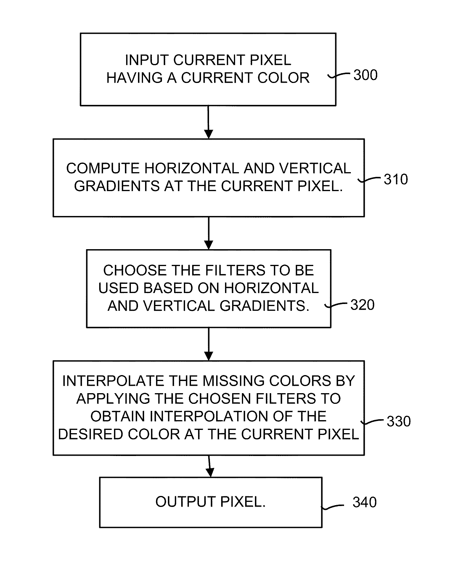
[0017]The invention disclosed herein includes a high-quality adaptive filter interpolation method and system for demosaicing of digital color images. The present invention overcomes the above-mentioned deficiencies of current interpolation techniques by providing a high-quality interpolation that is computationally efficient, fast, nearly optimal in a statistical sense, and provides superior image quality. Namely, the adaptive filter interpolation method and system disclosed herein uses color information from a current pixel and surrounding gradients to determine what type of interpolation filters should be used for each pixel in an image. This adaptive filter interpolation system and method is extremely efficient in that it allows all pixel colors in an image to be interpolated in one pass.
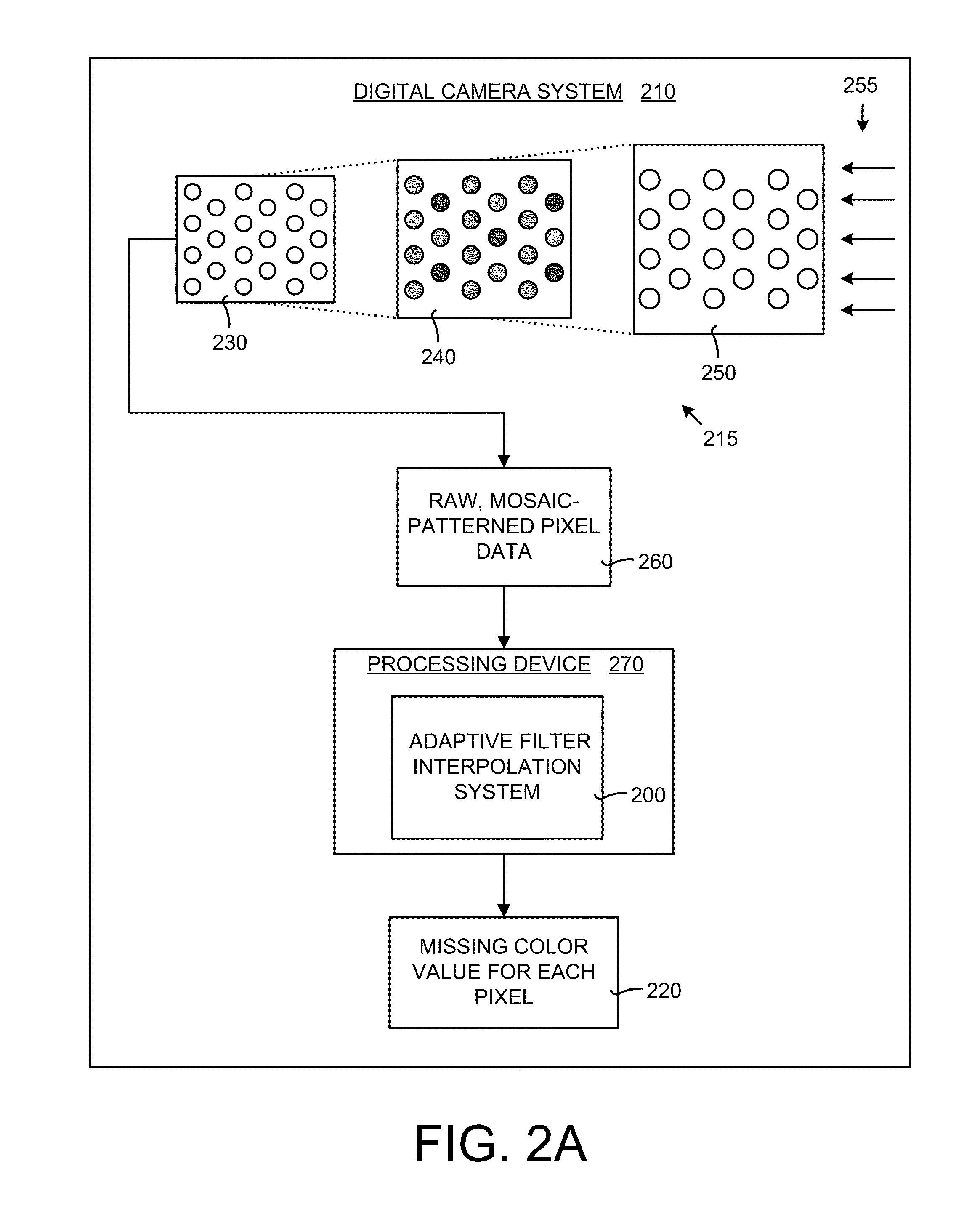
[0020]The adaptive filter interpolation method and system is an efficient new method to perform high-quality demosaicing. The coefficients of the filters used approximate statistically-optimal Wiener filters, and allow fast implementations that use no multiplication operations, just additions and shifts (although multiplications can be used if the processing hardware supports fast multiplications). The interpolated images generated with the adaptive filter interpolation system and method surpass the fidelity of most algorithms currently in use. Compared to other nonlinear interpolation algorithms, this adaptive interpolation system and method has the advantage that only a single pass is made over the image; all colors are interpolated during that pass. The better performing algorithms described in the references require two passes, one to interpolate green values, and another to interpolate red and blue values. A second pass is needed because the filters for red and blue interpolation use the interpolated green values. Plus, more passes may be needed to achieve a desirable quality level.

Problems solved by technology

One problem, however, with many bilinear interpolation techniques is that they generate significant artifacts in the color image.
Thus, while bilinear interpolation techniques are fast, computationally non-intensive, and easy to implement, they are also notorious for producing low-quality images due to the significant artifacts (mainly blurriness and color fringing) that they generate.
However, one problem with this technique by Freeman is that even at the expense of computing these ratios, the technique still produces visible artifacts.
Moreover, using complex operations (such as division and multiplication) in the computing of interpolations greatly increases the computational complexity, processing overhead, and implementation cost.
This technique is disadvantageous in that two computational passes are required to compute the missing color data in the image.
This requires two passes of the image in order to interpolate all red, green and blue color values which greatly increases the time necessary to interpolate the missing colors in an image.
One problem, however with the Gunturk technique is that it has a very high complexity (as many as 480 operations per input pixel).
Additionally, more than one pass across the image is required to interpolate the red, green and blue pixel values, making this technique slow and computationally inefficient.
A smaller region of support greatly reduces the image quality, while larger regions of support require more memory and greatly increase computational complexity.
However, the interpolated image quality sometime suffers when interpolation takes place across horizontal and vertical edges, and resulting interpolated images are still subject to artifacts at these points.

Method used


Image

  • System and method for adaptive interpolation of images from patterned sensors
  • System and method for adaptive interpolation of images from patterned sensors
  • System and method for adaptive interpolation of images from patterned sensors

Examples


working example

IV. Operational Details and Working Example

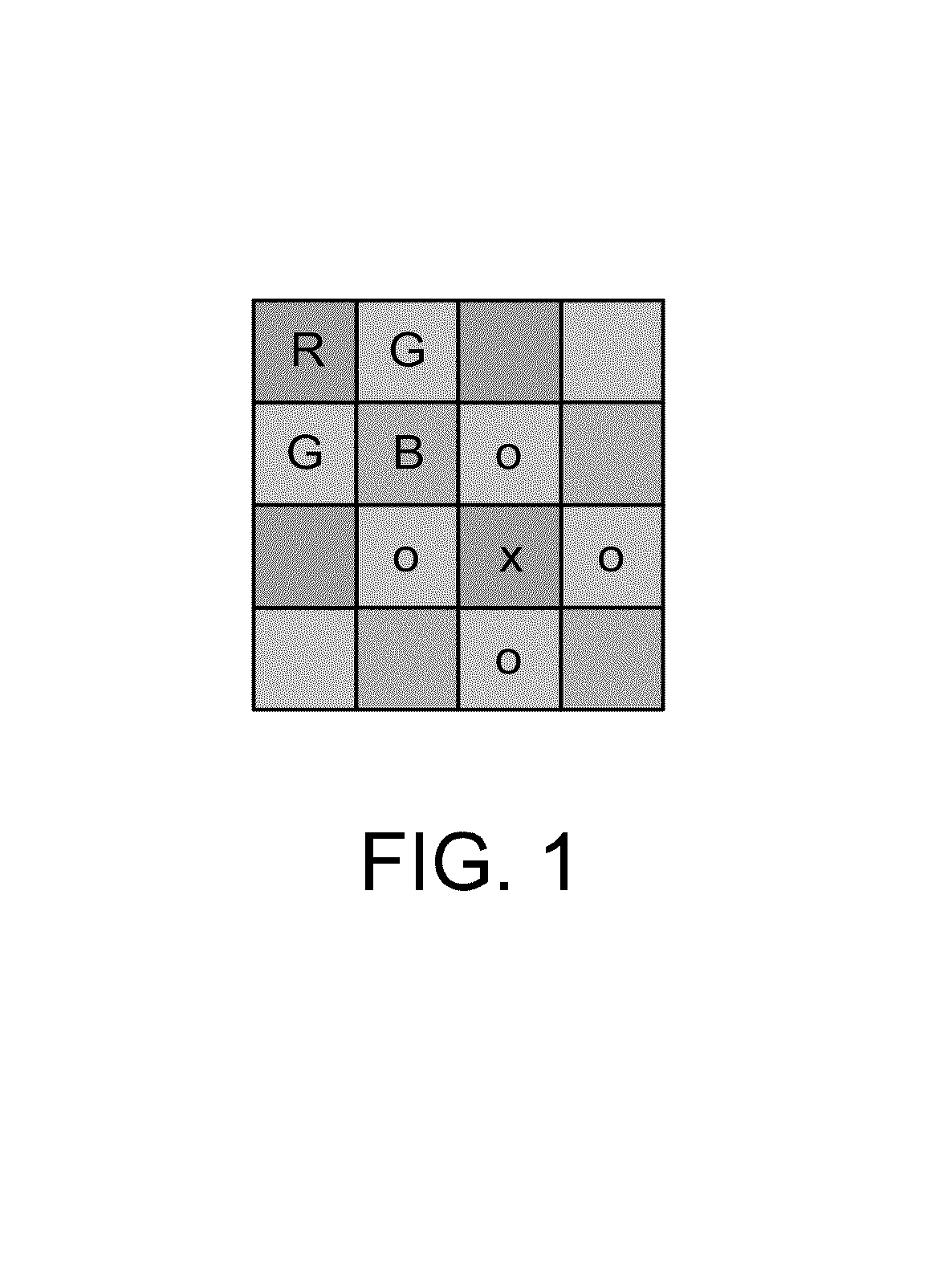
[0063]FIG. 4 is a general flow diagram illustrating a more detailed process than is described in FIG. 3. In particular, an image in Bayer (mosaiced) format is input (box 400). A pixel location is selected based on raster scan order and its pixel color is extracted (box 410). Next, for the given pixel location, the horizontal and vertical gradients are computed by employing a region of support around the pixel location (box 420). The region of support is defined as a size of a pixel neighborhood whose color values are considered for computations associated with any given pixel, such as the current pixel. A gradient differential, Gd, dependent on the pixel location is then computed (box 430). This gradient differential is computed using the current pixel (having a current color and pixel location) and pixels within the region of support. The gradient-differential, Gd, is then compared to a threshold T and the interpolation filters are selecte...


PUM


Abstract

A adaptive filter interpolation method and system for the demosaicing of color images. In general, input pixels are input in a Bayer-mosaiced pattern (only one color per pixel), and output pixels are in full RGB mode (three color values per pixel). For each pixel location, in raster scan order, the processing steps can be summarized as follows. Following a regular raster scanning order (from left to right and top to bottom), for each pixel location horizontal and vertical gradients are first computed (whose computation depends on the available color for that pixel), and from those the appropriate interpolation filters are chosen from a small set of predetermined filters. Then, the chosen filters are applied to interpolate the missing data.

Description

[0001]This is a continuation-in-part of application Ser. No. 10 / 801,450, filed Mar. 15, 2004 now U.S. Pat. No. 7,502,505 and entitled “HIGH-QUALITY GRADIENT-CORRECTED LINEAR INTERPOLATION FOR DEMOSAICING OF COLOR IMAGES”.TECHNICAL FIELD[0002]The present invention relates in general to processing of digital color images and more particularly to a method and system of adaptively applying filters to obtain a high-quality estimate of a missing pixel color at a pixel within the image.BACKGROUND OF THE INVENTION[0003]Digital cameras are steadily increasing in popularity due to their declining costs, which make them well within the reach of the average consumer. In order to keep costs low, many color digital cameras are single-sensor digital cameras in which only a single image sensor is used to capture color information for each pixel in a color image. Each image sensor in a single-sensor digital camera, which is typically a charge-coupled device (CCD) or a complementary metal oxide semic...

Claims


Application Information

Patent Timeline
Patent Type & Authority Patents(United States)
IPC IPC(8): G06K9/00G06T3/40H04N1/46G06T1/00H04N1/60
CPCG06T3/4015H04N23/12
Inventor MALVAR, HENRIQUE
Owner MICROSOFT TECH LICENSING LLC
Learn More