Light intensity adjusting system

a technology of light intensity and adjustment system, which is applied in the field of light intensity adjustment system, can solve the problems of specific risk of variance in the detection of defects, deleterious effect on the accuracy of detecting defects, image deterioration, etc., and achieve the effect of improving scan accuracy, reducing or making unnecessary image compensation processing, and positive generating

Inactive Publication Date: 2010-01-05
CCS INC
View PDF17 Cites 3 Cited by
  • Summary
  • Abstract
  • Description
  • Claims
  • Application Information

AI Technical Summary

Benefits of technology

[0011]Thus, the present invention is a device that attempts to change the approach and control the light irradiation device such that, when the camera incorporates the image, for example, the brightness of the target area of that image is made uniform, or unevenness is positively generated; and by greatly reducing or making unnecessary the image compensation processing by the image processor side, addresses the problems of interest, namely, to improve scan precision by preventing false detection that can be generated when conducting compensation processing on that image; and to shorten scan time.
[0014]With this kind of device it is possible to prevent diminishing scan precision caused by image deterioration when compensating because it is possible to greatly reduce or make unnecessary image compensation processing, such as shading compensation by the image processor side. In addition is becomes possible to broadly promote shortening scan time and improving scan precision because the image processing device can concentrate on the original image processing necessary for scanning.

Problems solved by technology

Nonetheless, when conducting shading compensation on the image processor side, there is the risk that image deterioration when converting the digital signals and differences in the calculation method during compensation may have a deleterious effect on the precision of detecting defects, etc.
When, for example, shading compensation is conducted from the image processor side with said addition and subtraction making the brightness levels of the whole uniform, as indicated in FIG. 25, a difference in those brightness levels may be generated because only the background is compensated and no changes are generated in the relative level of the defect from the background, irrespective of the central part and the edge having the same defect, and thus there is the specific risk of variance in the detection of defects.
However, gain control also amplifies noise near the edge, and produces the risk of mistakenly detecting this noise as a defect.
Further, because the load on the image processing side becomes larger, there is a resulting disadvantage that the scan time cannot be shortened without shortening the image processing time; and there is also the disadvantage that costs will increase if the scale of the image processor is increased.

Method used


Image

  • Light intensity adjusting system
  • Light intensity adjusting system
  • Light intensity adjusting system

Examples


first embodiment

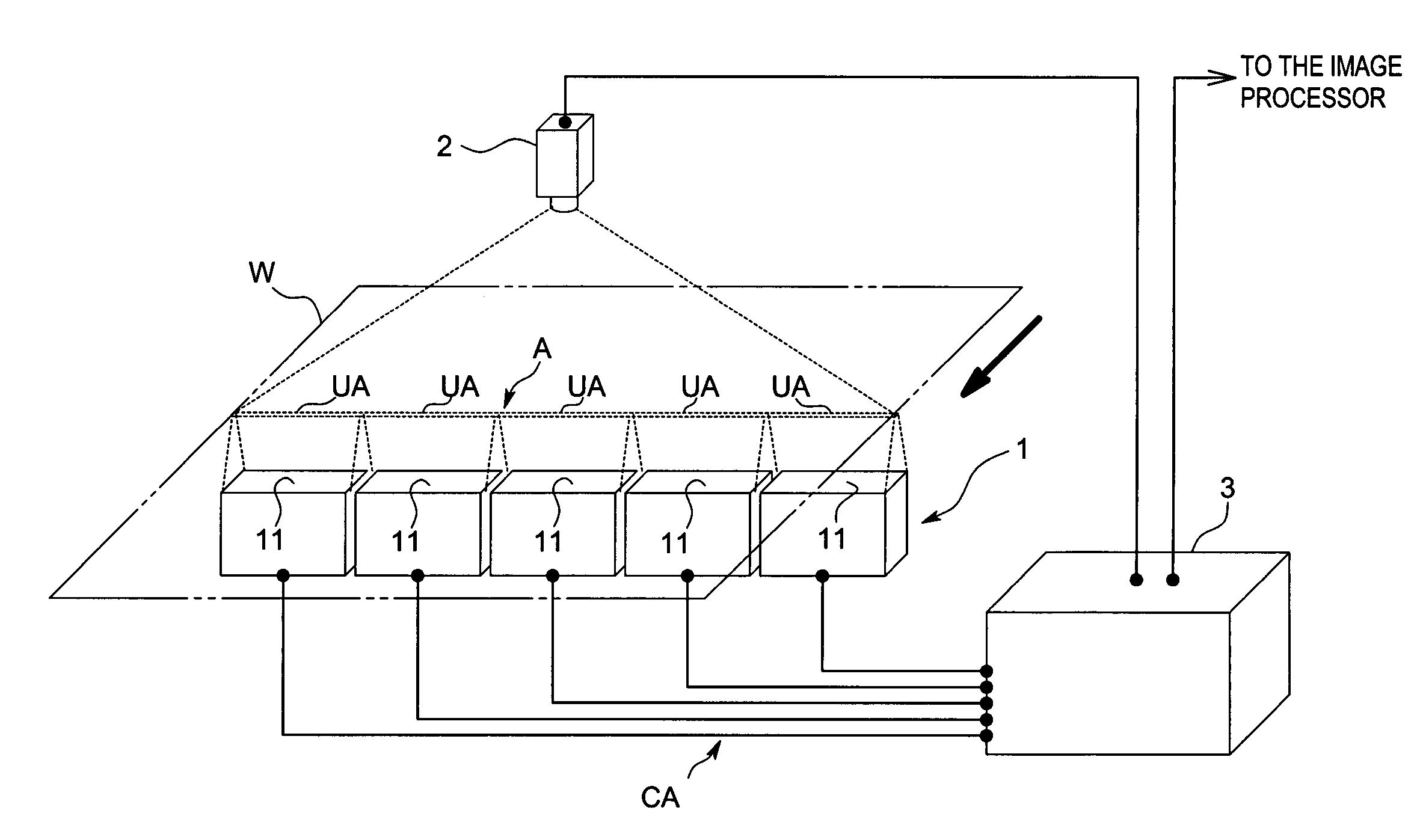
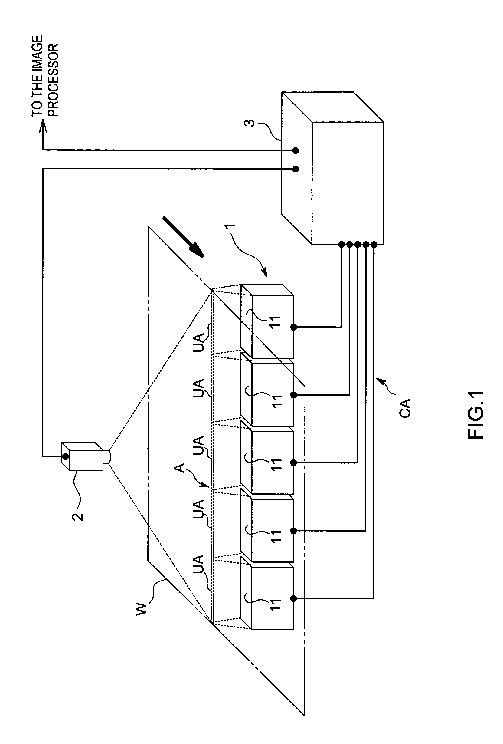
[0054]FIG. 1 indicates an overall summary of a light intensity control system related to the present embodiment. This light intensity control system is, for example, used in a surface scan of a product, etc.; the scan object (work piece) W of the present invention is, for example, a continuous object such as translucent paper or film; and is set up to flow in a predetermined direction at a fixed speed.

[0055]Accordingly, as indicated in the same diagram, this light intensity control system comprises: a light irradiation device 1 that has multiple independently light intensity adjustable light irradiation units 11, and irradiates light toward the back surface predetermined region of said work piece W; a photographic device 2 that photographs the light irradiated predetermined target area A from the front surface through a lens not indicated in the diagram, and outputs target area images, which are the photographed images; and a light intensity control unit 3 that controls the respecti...

second embodiment

[0069]Next, a second embodiment of the present invention will be explained based on the diagrams. Further, in the following explanation the same codes will be used for members that correspond to those of said first embodiment.

[0070]The light irradiation system of this second embodiment has nearly the same configuration as that of said first embodiment. However, there is a slight difference in the configuration of the functions of the light intensity control unit 3. The explanation below will concentrate on the points of difference from the first embodiment, and an explanation of common points will be omitted.

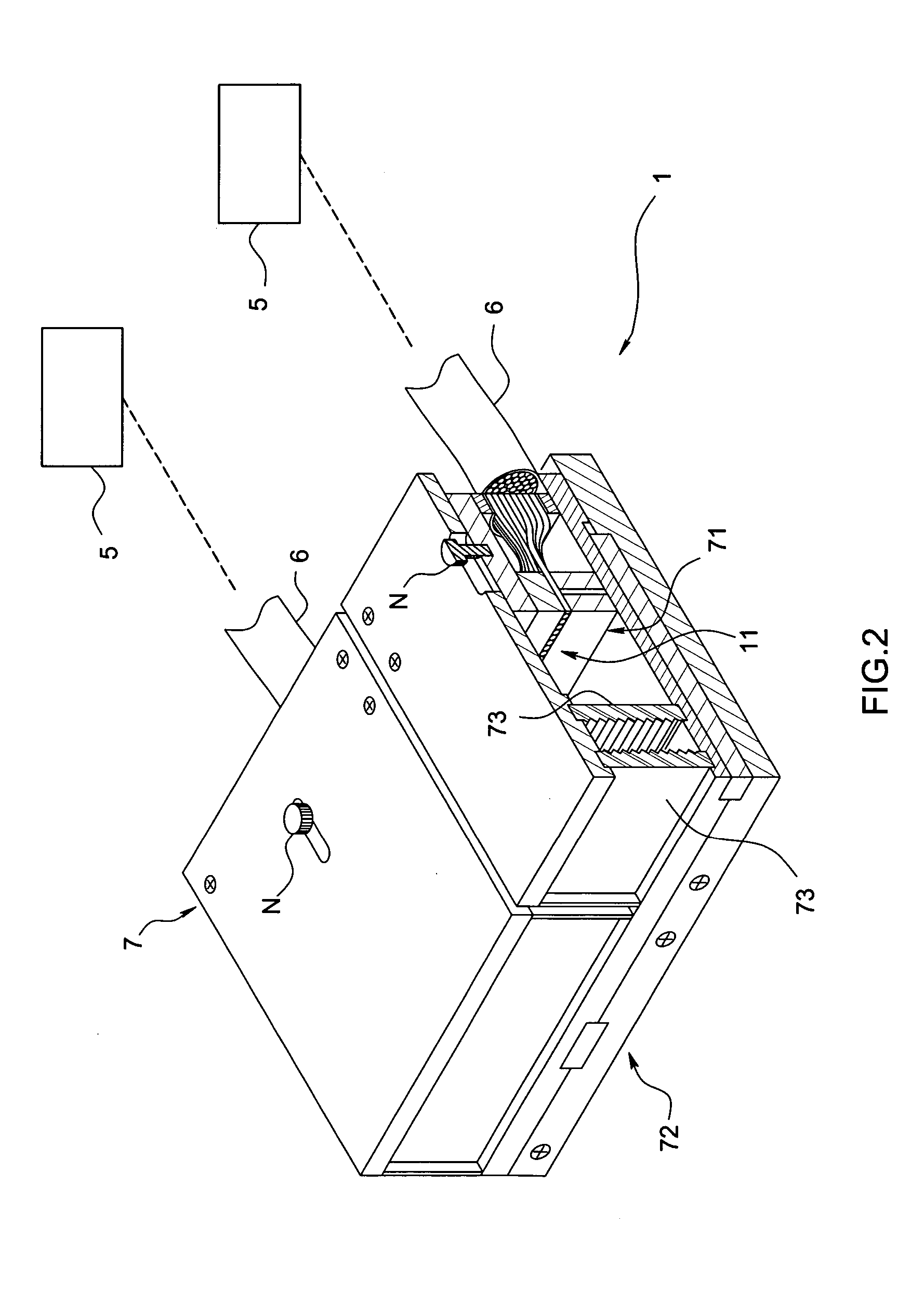
[0071]The light intensity control unit 3 of this embodiment is connected to the various power LEDs 5 through current cable CA, and controls the current supplied to these. As indicated in the functional block diagram in FIG. 8, comprises: a power source 35; an image separation unit 31 that separates said image signals into unit area image signals for every unit area UA; represent...


PUM

PropertyMeasurementUnit
currentaaaaaaaaaa
light intensityaaaaaaaaaa
areaaaaaaaaaaa

Abstract

A light intensity adjustment system is provided which greatly decreases or makes unnecessary image compensation by the image processing device side, improves scan precision, and can reduce the scan time; and which comprises: a light irradiation device 1 that has multiple independently light intensity adjustable light irradiation units 11, and that irradiates light facing a predetermined target area A; a photographic device 2 that photographs said target area A through a lens, and outputs a target area image that is the photographed image; and a light intensity control unit 3 that controls the respective light intensities of said light irradiation units 11 so that the brightness of the various parts of the target area images that said photographic device 2 has output approaches a predetermined standard value.

Description

TECHNICAL FIELD[0001]The present invention is related to a light intensity adjustment system for adjusting the light intensity to irradiate when conducting external appearance scans and defect scans by photographing the target area of a work piece.BACKGROUND ART [0002]In the past, when conducting inline high-speed scans of WEB (continuous objects: film, paper, sheet metal) and BATCH (sheet products, individual products: cut film, cut glass, drums), which are the objects to be scanned, scans for surface defects were conducted by using line sensor cameras, incorporating the surface of the flowing work pieces as continuous image data, and, with an image data processor, detecting areas that differ in brightness.[0003]At that time, in order to precisely detect surface faults, it was necessary to illuminate uniformly with a fixed illumination intensity the area targeted for photography by said camera, and conventionally halogen lamps and fluorescent lights were used as the light irradiat...

Claims


Application Information

Patent Timeline
Patent Type & Authority Patents(United States)
IPC IPC(8): G03B9/70G03B15/03G01N21/89
CPCG01N21/8903G01N2021/8896
Inventor YONEDA, KENJIHIROOKA, SHIGEHIDE
Owner CCS INC
Why Eureka
Try Eureka