Fluid-assisted medical device

a technology of fluid-assisted medical devices and electrodes, which is applied in the field of electrosurgical devices and methods of treating body tissues, can solve problems such as tissue desiccation, tissue sticking to electrodes, and unintended thermal damage to tissue,

Inactive Publication Date: 2010-01-12
MEDTRONIC ADVANCED ENERGY
View PDF973 Cites 358 Cited by
  • Summary
  • Abstract
  • Description
  • Claims
  • Application Information

AI Technical Summary

Benefits of technology

[0009]In a preferred embodiment, the first arm and second arm include at least one groove that surrounds the at least one solution infusion opening. Preferably, the groove(s) include spaced exit slots to allow conductive solution to exit the groove during use (e.g., when pressure is applied to tissues). The grooved arm serves to isolate the metal electrode from direct contact with bodily tissues being treated. Additionally, the grooved configuration provides constant spacing between the electrode and tissue to be treated. Further, the groove assists in preventing tissue pressure against the solution infusion openings during squeezing of the arms of the device, which could inhibit or reduce the flow of electrically conductive fluid locally.
[0013]The invention provides a combination of advantages. For example, the device provides conductive solution, such as saline, at the electrode-tissue interface to limit the peak tissue temperature, preferably to 100° C. or less. The provision of saline at the interface prevents tissue desiccation and the various effects of desiccation, such as tissue sticking to the electrodes, perforation of adjacent organs or tissue structures, char formation on electrodes and adjacent tissue, and smoke formation. The saline at the interface preferably maintains peak tissue temperature at or below 100° C. by (1) providing coupling of the electrode to the tissue with a wetted contact area that is much larger than that of a dry electrode, thus reducing current density and local RF heating near the electrode-tissue interface, (2) providing a convective cooling effect, such that the flowing liquid saline is heated by the warmer surface of RF-heated tissue, and (3) providing an evaporative cooling effect, such that excess RF power that cannot be conducted or convected away from the target tissue will be used to boil some fraction of the saline provided to the treatment surface.
[0015]The invention further provides a multi-purpose instrument that can be used to provide both coagulation and cutting of tissue without having to be removed from the patient's body. In one embodiment, the instrument is fabricated so that it is capable of sealing and cutting a vessel, as well as causing surface hemostasis on tissue such as bleeding liver.

Problems solved by technology

Current electrosurgical devices can cause the temperature of tissue being treated to rise significantly higher than 100° C., resulting in tissue desiccation, tissue sticking to the electrodes, tissue perforation, char formation and smoke generation.
Undesirable results of such transmission to adjacent tissue include unintended thermal damage to the tissue.
One limitation of current electrosurgical devices arises from size constraints and dimensions.
It is difficult to reach or gain access to some tissue and vessels due to anatomy and size constraints.
Hinged jaws reduce visibility of the tip and often limit grasping capability of vessels due to force constraints.
Further, devices currently used also often have long rigid shafts that cannot bend to maneuver around anatomical “tight” spots.
Multiple instrument passes are undesirable because they (1) waste valuable operating room time, (2) sometimes make it difficult to precisely relocate the target treatment site, (3) increase the risk of infection, and (4) increase the cost by increasing the number of different surgical instruments that are needed to complete the surgical procedure.

Method used


Image

  • Fluid-assisted medical device
  • Fluid-assisted medical device
  • Fluid-assisted medical device

Examples


Embodiment Construction

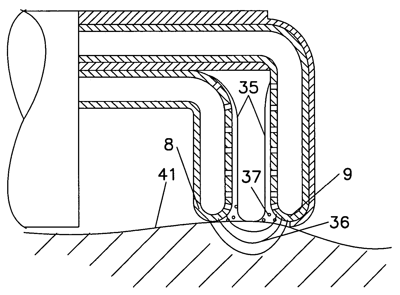
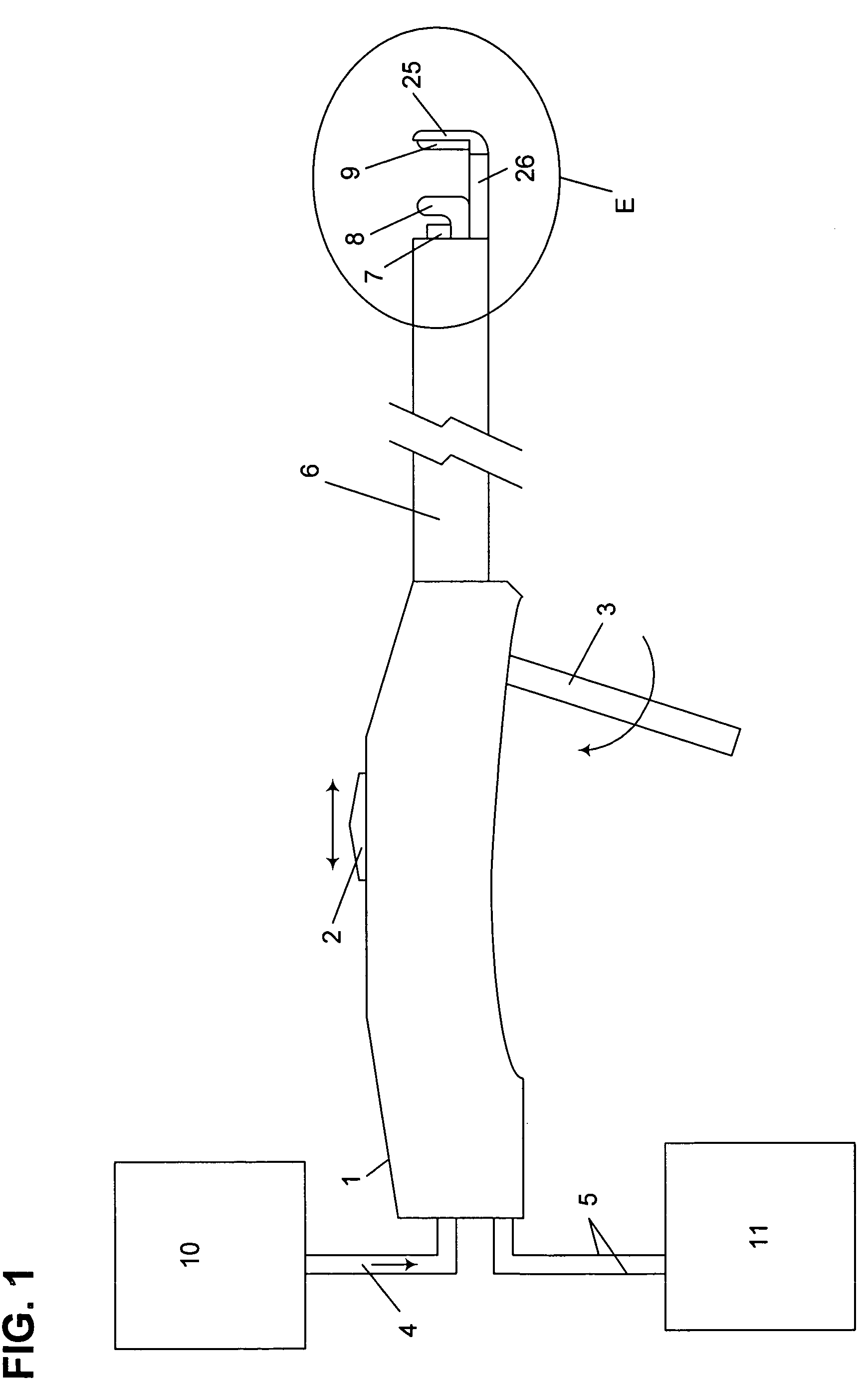
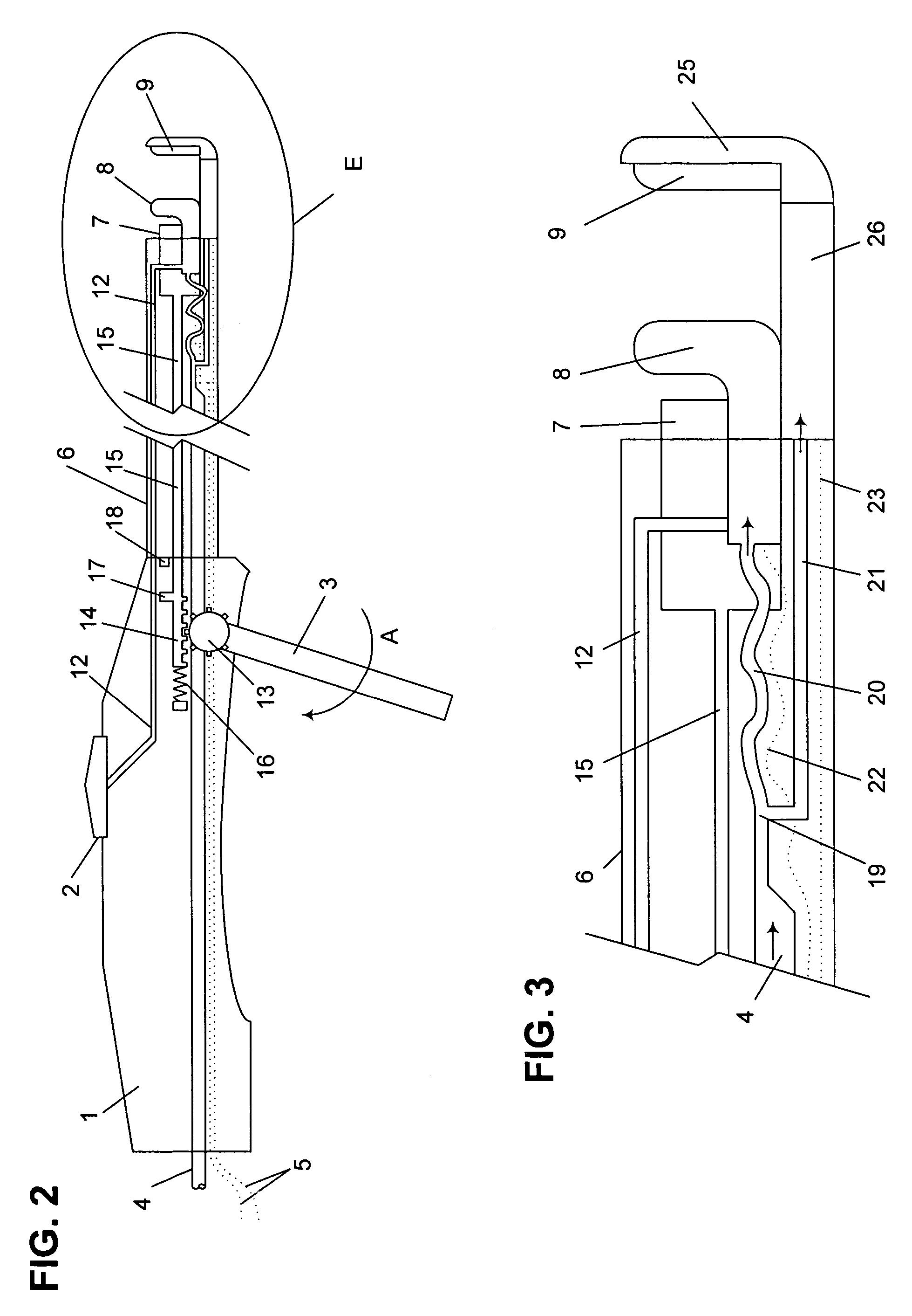
[0055]The invention provides a medical device that comprises a first electrode and a second electrode, wherein the electrodes are disposed coaxially to each other, and at least one of the electrodes is translationally movable. Preferably, the first electrode is provided on a first arm, and the second electrode is provided on a second arm of the device. According to the invention, the device comprises at least one translationally movable arm that can be selectively movable to a fixed position. Preferably, the device includes a locking mechanism, to allow the operator to move at least one arm of the device to a desired position and lock the arm in that position. Each electrode is provided with conductive solution. In a preferred embodiment, the electrodes include at least one groove to assist in delivery of the conductive solution to tissue.

[0056]In a preferred embodiment, the invention provides a medical device comprising a housing having a proximal and a distal end; a tubular member...


PUM


Abstract

The invention provides a medical device that includes a housing, a tubular member extending from the distal end of the housing, a first arm extending from the distal end of the tubular member, the first arm including a first electrode, a second arm extending from the distal end of the tubular member, the second arm including a second electrode and being disposed coaxially with the first arm, at least one solution infusion opening on each electrode, and a solution delivery channel for delivery of a conductive solution to the solution infusion openings. According to the invention, at least one of the first arm or the second arm is translationally moveable, and at least one of the first arm or the second arm is adapted to be coupled to a source of radiofrequency energy. The invention also provides a corresponding method for treating blood vessels or other tissues of the body.

Description

[0001]This application is a continuation of U.S. application Ser. No. 10 / 354,643, filed Jan. 29, 2003, which is a continuation of U.S. application Ser. No. 09 / 668,403, filed Sep. 22, 2000, now U.S. Pat. No. 6,558,385. The entire disclosure of these applications is incorporated by reference.FIELD OF THE INVENTION[0002]This invention relates generally to the field of devices for use in surgery upon tissues of the body. More particularly, the invention relates to an electrosurgical device and methods of treatment of body tissues.BACKGROUND OF THE INVENTION[0003]Electrosurgical devices use electrical energy, most commonly radiofrequency (RF) energy, to cut tissue and / or cauterize blood vessels. During use, a voltage gradient is created at the tip of the device, thereby inducing current flow and related heat generation in the tissue. With sufficiently high levels of electrical energy, the heat generated is sufficient to cut the tissue and, advantageously, to cauterize severed blood vesse...

Claims


Application Information

Patent Timeline
Patent Type & Authority Patents(United States)
IPC IPC(8): A61B18/18A61B18/12A61B17/125A61B18/00A61B18/14
CPCA61B18/1442A61B17/32A61B2017/2945A61B2018/00029A61B2018/00196A61B2018/00404A61B2018/1472A61B2018/00601A61B2018/1412A61B2018/1432A61B2018/145A61B2018/1455A61B2018/00589
Inventor MCCLURKEN, MICHAEL E.LUZZI, ROBERT
Owner MEDTRONIC ADVANCED ENERGY
Why Eureka
Try Eureka