Plasma coating system for accommodating substrates of different shapes

a technology of coating system and substrate, applied in the direction of coating, molten spray coating, plasma technique, etc., can solve the problems of not being able to provide two-sided coating or accommodating non-planar substrates

Active Publication Date: 2010-01-12
EXATEC LLC
View PDF17 Cites 14 Cited by
  • Summary
  • Abstract
  • Description
  • Claims
  • Application Information

AI Technical Summary

Benefits of technology

[0005]Further features and advantages of the invention will be apparent from the following description and from the claims.

Problems solved by technology

Such a configuration cannot accommodate non-planar substrates or provide two-sided coating.

Method used


Image

  • Plasma coating system for accommodating substrates of different shapes
  • Plasma coating system for accommodating substrates of different shapes
  • Plasma coating system for accommodating substrates of different shapes

Examples


Embodiment Construction

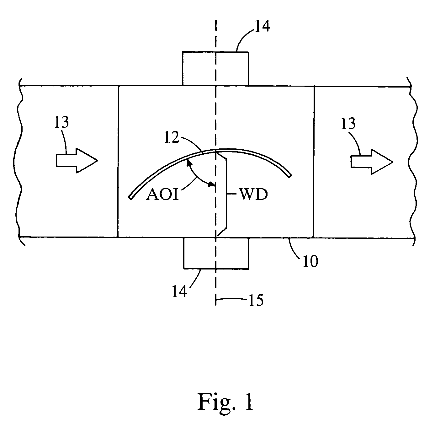
[0011]Referring now to FIG. 1, there is shown a linear coating station 10 in which a substrate 12 follows a fixed linear path through the coating station, as indicated by the arrows 13. The substrate may be a component for an automotive vehicle. For example, the substrate may be a rear window or roof panel made of polycarbonate.

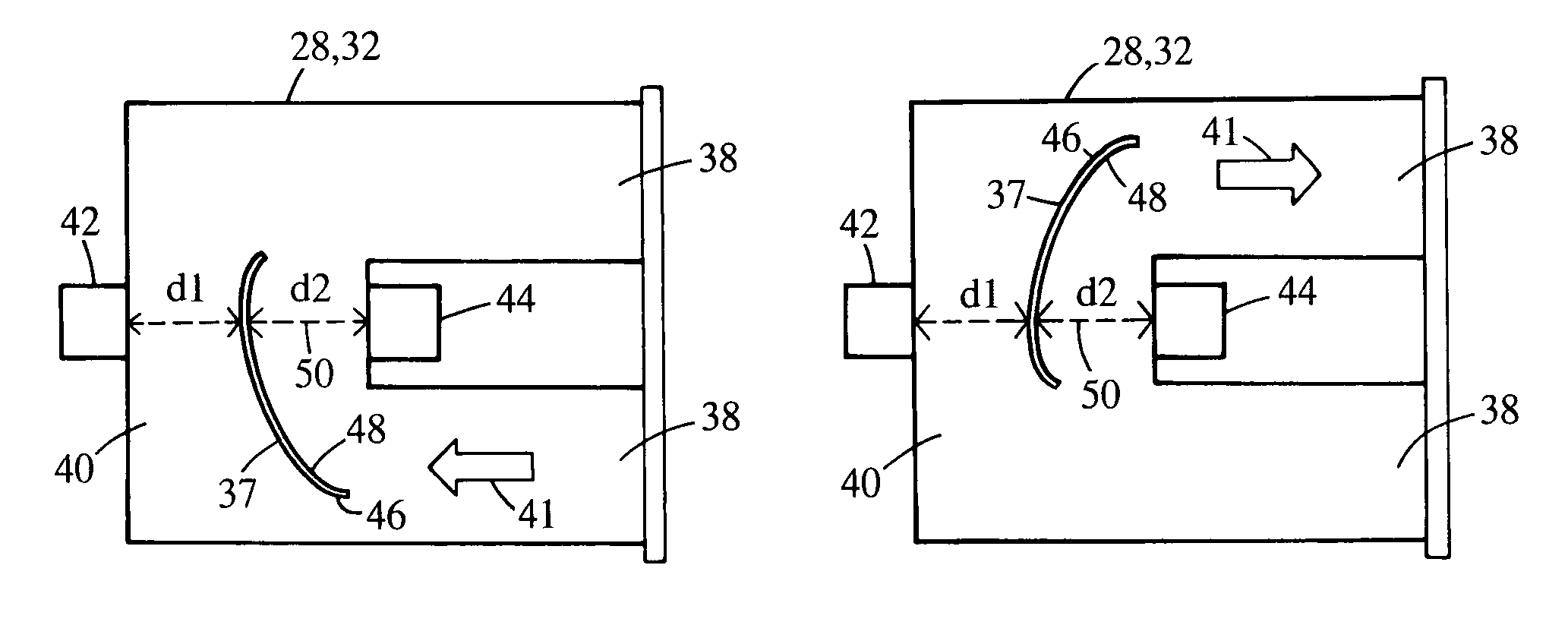
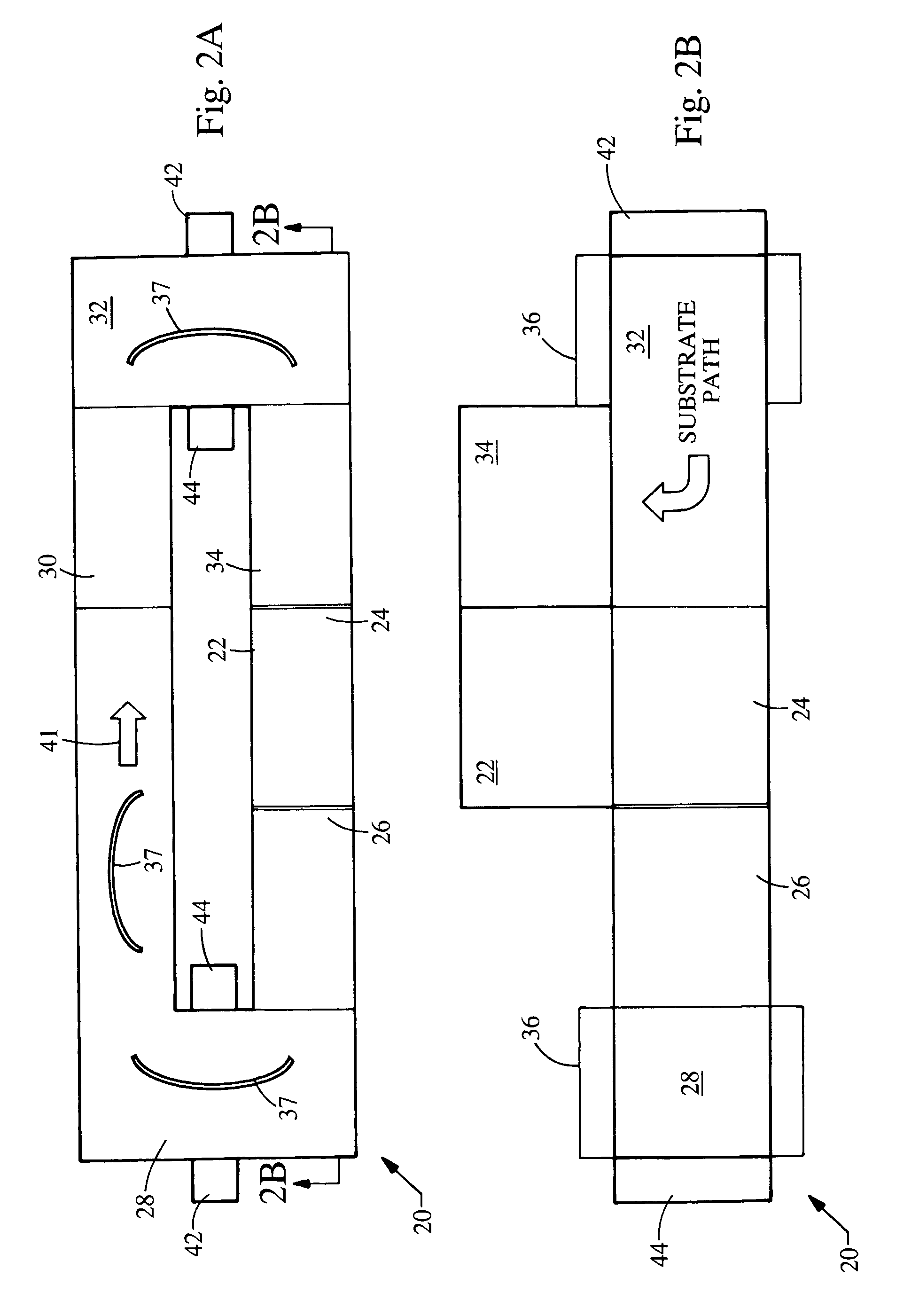
[0012]The coating station 10 includes a pair of plasma arcs or a pair of arrays of arcs 14 (extending into the page of FIG. 1 as viewed from the top of the coating station 10) on opposite sides of the coating station 10, as well as associated reagent manifolds for providing reagents to the coating process. The coating station 10 may be associated with one or more heaters located upstream of the coating station to heat the substrate before it enters the coating station. An additional coating station may be located downstream of the coating station to provide further plasma coating capabilities, in which case another heater may be located between the two coatin...


PUM

PropertyMeasurementUnit
angle of incidenceaaaaaaaaaa
working distanceaaaaaaaaaa
distanceaaaaaaaaaa

Abstract

A plasma coating system includes at least one coating station with a first side and a second side defining a pathway with at least one bend. The coating station also includes a first plasma arc that provides a plasma jet directed towards a substrate. The first plasma arc is positioned on either the first side or the second side of the bend.

Description

BACKGROUND[0001]The present invention relates to a plasma coating system. More specifically, the invention relates to a system that accommodates substrates of different shapes.[0002]In some plasma coating systems, as horizontally oriented substrates advance through a coating station and remain in a horizontal plane, plasma arcs arranged above the substrates direct plasma jets entrained with one or more reagents toward the substrates. Such a configuration cannot accommodate non-planar substrates or provide two-sided coating.[0003]Other plasma coating systems are arranged in a linear manner with the substrates following a fixed linear path through the coating station or coater. The coating station is typically provided with one or more reagent manifolds and plasma arcs that direct plasma jets entrained with reagents at one or both sides of the substrate. As a non-planar substrate passes through the coating station in such systems, the distance between the surface of the substrate and ...

Claims


Application Information

Patent Timeline
Patent Type & Authority Patents(United States)
IPC IPC(8): B05D1/08C23C16/00C23C4/00B05D7/24B29C59/14C23C4/12C23C16/04
CPCC23C4/127C23C16/513C23C16/54B29C59/142C23C4/134B05D7/24B29C59/14C23C4/12C23C16/04
Inventor GASWORTH, STEVEN M.
Owner EXATEC LLC
Why Eureka
Try Eureka