System for monitoring electrical equipment and providing predictive diagnostics therefor

a technology for electrical equipment and predictive diagnostics, applied in the field of electrical equipment systems, can solve problems such as maintenance and planned outages, and achieve the effect of prolonging the life of electrical equipmen

Active Publication Date: 2010-01-12
EATON INTELLIGENT POWER LTD
View PDF6 Cites 26 Cited by
  • Summary
  • Abstract
  • Description
  • Claims
  • Application Information

AI Technical Summary

Benefits of technology

[0012]There is now a much greater need and desire for “predictive maintenance” whereby electrical equipment is evaluated while being energized and operating. This results in outages being planned and maintenance being performed only on electrical equipment in need, rather than the traditional across-the-board maintenance of entire systems. Hence, there is also a need to retrofit existing electrical equipment with “predictive tools” as well as provide such tools on new electrical equipment. Predictive tools provide an early warning of an immediate or potential failure and the need for near-term maintenance to either prevent a pending failure or to prolong the life of the electrical equipment.
[0013]These needs and others are met by embodiments of the invention, which address both the need to identify immediate or potential failures of electrical equipment and, also, the need for immediate inspections and / or maintenance to be performed. The combination of these two functions help to satisfy end-user needs to operate electrical equipment more continuously for relatively longer periods of time, thereby improving overall production efficiency at reduced costs, and can effectively change the current process of time-based or usage-based maintenance or inspection cycles.

Problems solved by technology

This results in outages being planned and maintenance being performed only on electrical equipment in need, rather than the traditional across-the-board maintenance of entire systems.

Method used


Image

  • System for monitoring electrical equipment and providing predictive diagnostics therefor
  • System for monitoring electrical equipment and providing predictive diagnostics therefor
  • System for monitoring electrical equipment and providing predictive diagnostics therefor

Examples


example 1

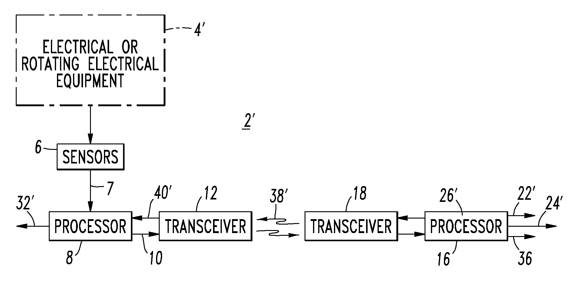
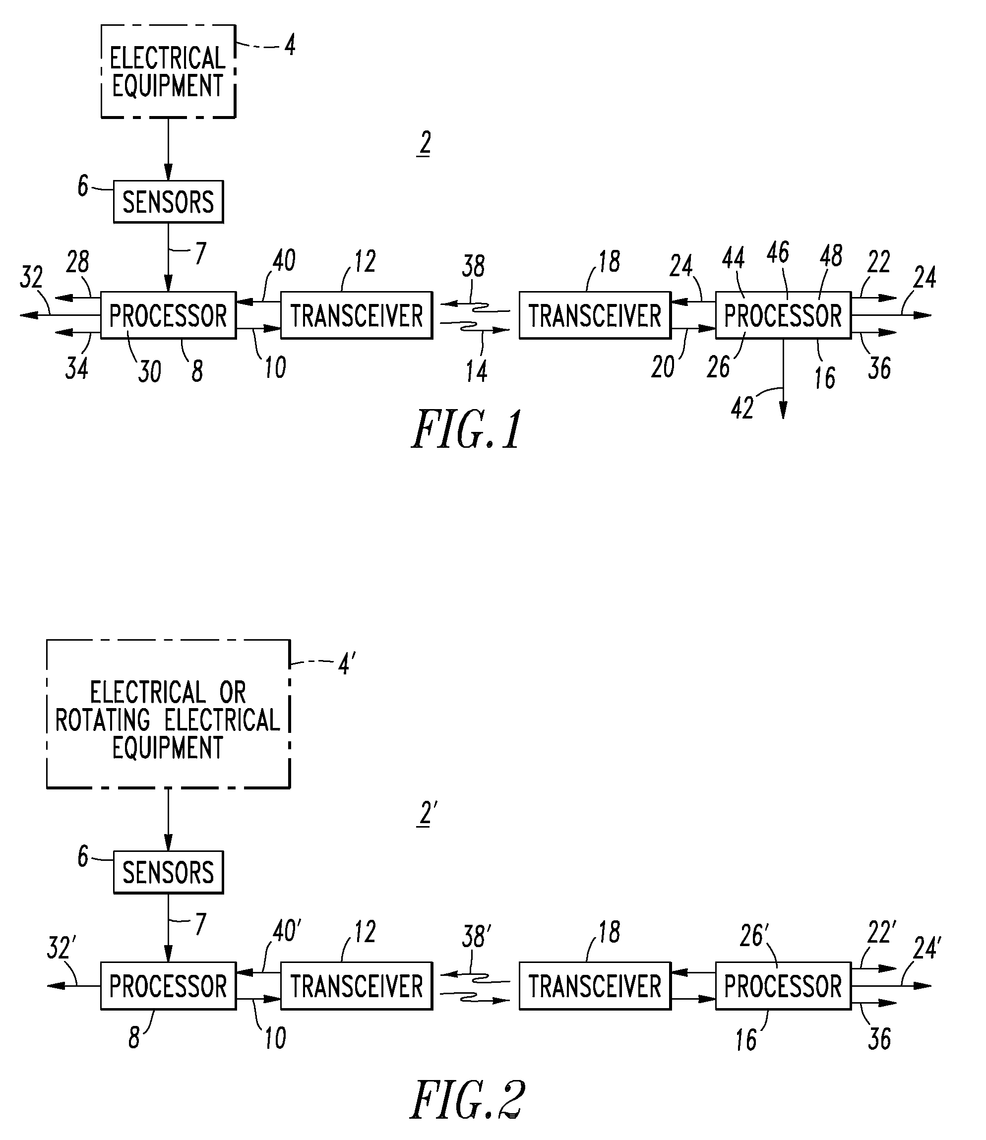
[0040]The first and second transceivers 12,18 are structured to communicate through one of the group consisting of a global communication network (e.g., the Internet), a cellular telephone network, and a wired telephone network.

example 2

[0041]The first processor 8 is structured to periodically receive the sensed information 7 from the number of sensors 6. The first transceiver 12 is structured to periodically transmit the transmitted information 14 to the second transceiver 18.

example 3

[0042]The first processor 8 is structured to provide a number of notifications 28 responsive to the number of alarms 26. In this example, the alarms 26 are communicated from the second processor 16 to the first processor 8 by the transceivers 18,12. Alternatively, a number of alarms 30 may be provided by the first processor 8, in which case the number of notifications 28 are responsive to the number of alarms 30.


PUM


Abstract

A system monitors electrical equipment and provides predictive diagnostics therefor. The system includes sensors located at or about the electrical equipment. The sensors sense information pertaining to operation of the electrical equipment. A first processor is located at or about the electrical equipment and receives the sensed information from the sensors as first information. A first transceiver cooperates with the first processor to transmit the first information as transmitted information. A second processor is located remote from the electrical equipment. A second transceiver cooperates with the first transceiver to receive the transmitted information as second information and communicate the same to the second processor. The second processor provides a notification pertaining to an immediate inspection and / or maintenance of the electrical equipment, and set points operatively associated with the sensed information. The set points pertain to a number of potential alarms regarding operation of the electrical equipment.

Description

BACKGROUND OF THE INVENTION[0001]1. Field of the Invention[0002]This invention pertains generally to systems for electrical equipment and, more particularly, to such systems that monitor and provide predictive diagnostics for electrical equipment. The invention also pertains to systems that monitor and provide predictive diagnostics for electrical or rotating electrical equipment.[0003]2. Background Information[0004]Today, electrical equipment users are being stretched to do more with less. This translates into lower maintenance budgets and an operating mode of “outages are no longer an option”. Electrical equipment is conventionally maintained on a periodic basis. Known predictive technology for electrical equipment includes thermographic, ultrasonic and partial discharge detection and inspections.[0005]Thermographic and ultrasonic detection are applied at all voltage levels, while partial discharge detection is applied to medium voltage systems. Ultrasonic and partial discharge in...

Claims


Application Information

Patent Timeline
Patent Type & Authority Patents(United States)
IPC IPC(8): G08B21/00
CPCG01R31/343G01R31/025G01R31/1263G01R31/52
Inventor PAOLETTI, GABRIEL J.NINE, THOMAS M.HERMAN, GEORGE M.STEPHENS, MARK T.YANNIELLO, ROBERT
Owner EATON INTELLIGENT POWER LTD
Why Eureka
Try Eureka