
Closely-spaced multiple targets detection using a regional window as a discriminant function

a regional window and discriminant function technology, applied in the field of unresolved target detection using an infrared focal plane array, can solve problems such as inability to deal well with target phasing problems, inability to guarantee, and problems in real-world applications, and achieve the effect of simple and reliable approach

Inactive Publication Date: 2010-01-12
LOCKHEED MARTIN CORP
View PDF2 Cites 2 Cited by
  • Summary
  • Abstract
  • Description
  • Claims
  • Application Information

AI Technical Summary

Benefits of technology

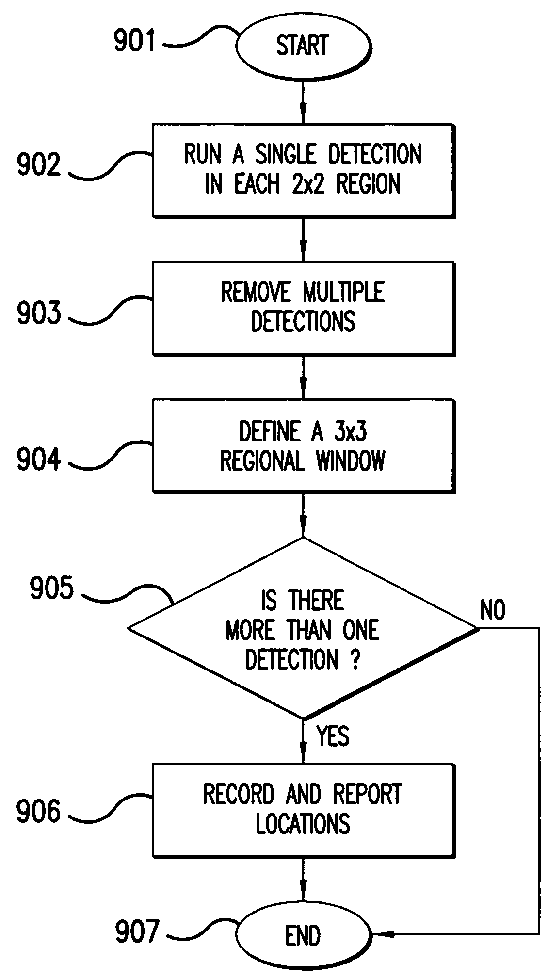
[0007]The method and system of the present invention, provides a simple and reliable approach for detecting closely spaced objects. More specifically, a sensor images a scene, and it provides image data to a processor which runs a plurality of algorithms for processing the image data. A first algorithm, having a predetermined CFAR, determines whether there are any single object detections within the scene. A second algorithm, having substantially the same predetermined CFAR and having at least a first regional window corresponding to a matrix of pixels, determines whether there are closely spaced objects within the regional window. This algorithm can be run by using a regional moving window across the whole image. The closely spaced objects detected within the regional window are recorded and reported.

Problems solved by technology

The traditional approach for CSO detection is more of a scientific approach, and it has problems in real world applications.
For example, the traditional approach needs initial guesses of target numbers, and it does not deal well with target phasing problems.
Moreover, it is not guaranteed to always find the global minimum, and it requires heavy computations for large iterations that do not always converge.

Method used


Image

  • Closely-spaced multiple targets detection using a regional window as a discriminant function
  • Closely-spaced multiple targets detection using a regional window as a discriminant function
  • Closely-spaced multiple targets detection using a regional window as a discriminant function

Examples


Embodiment Construction

[0017]In order to facilitate the reader's understanding of the present invention, the following list of acronyms and their general meanings are provided:[0018]ATR—Automatic Target Recognition[0019]CFAR—Constant False Alarm Rate[0020]CSOs—Closely Spaced Objects[0021]EOTDS—Electro-Optical Targeting Demonstration System[0022]FPA—Focal Plane Array[0023]IR—Infrared[0024]LS—Least-Square[0025]Pd—Probability of Detection[0026]Pdec—Probability of Target Detection[0027]Pfa—Probability of False-Alarm[0028]Pfa(Sngl) Probability of False-Detection for a Single Target[0029]Pfa(CSO) Probability of False-Detection for a CSO Target Pair[0030]ROC—Receiver Operating Characteristics[0031]SNR—Signal-to-Noise Ratio[0032]SCNR—Signal to Clutter Noise Ratio

[0033]The present invention includes reliable CSO detection algorithms using a regional window (3×3 or 5×5) as a discriminant function to distinguish single targets from CSO targets. The idea behind this approach is that the chance (probability) of the fa...


PUM


Abstract

A method and system, for detecting closely spaced objects with data from an imaging sensor. A CFAR detector performs detection on the image data at a threshold level. A processor runs a first algorithm on exceedances above the CFAR threshold. The first algorithm is for single target detection and includes a local-max algorithm that identifies multiple exceedances within a 2×2 matrix of image data and only keeps exceedance with the maximum value. All other exceedances in image are single target detections. The processor runs a second algorithm that identifies multiple exceedances (single target detections) within a local regional area across the whole image. The regional area size may be a 3×3, 4×4, or 5×5 matrix depending on the specified CSO separations. This algorithm may use a regional moving window across the whole image. An alternative method using the indices of all the exceedances' (x,y) coordinates is also disclosed.

Description

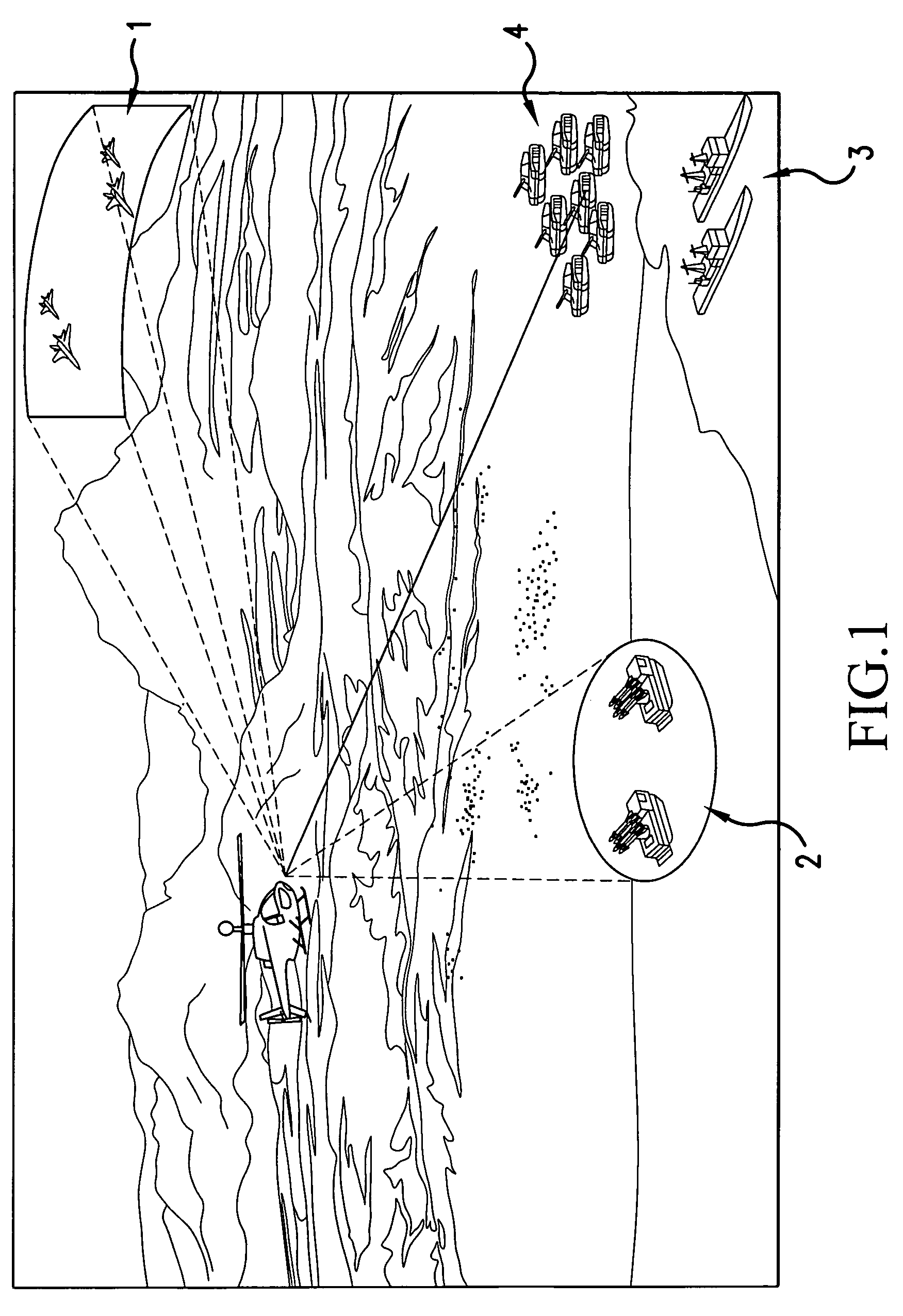
BACKGROUND OF THE INVENTION[0001]1. Field of the Invention[0002]The present invention relates generally to unresolved target detection using an infrared focal plane array (IR FPA), and it more particularly relates to the detection of closely spaced multiple targets using a regional window as a discriminant function.[0003]2. Description of the Related Art[0004]In general, most current military sensors use single target detection and tracking approach. However, in many battlefield scenarios targets show up as closely-spaced pairs or groups. For example as shown in FIG. 1, air fighters 1 almost always come as a pair that includes a leading fighter and an accompanying fighter. Frequently, ballistic missiles 2 are launched in pairs or groups located in a closely-spaced area. Navy warships 3 usually move as a fleet (ship group), and army trucks and tanks 4 on a large scale battlefield move and show up in teams and groups, as shown in FIG. 1. Therefore, the capability to detect and track C...

Claims


Application Information

Patent Timeline
Patent Type & Authority Patents(United States)
IPC IPC(8): G06K9/00G06V10/36
CPCG01S3/7864G06K9/3241G06K9/4609G06K9/56G06T7/004G01S13/726G06T2207/10048G06T2207/30212G06T7/70G06V10/255G06V10/443G06V10/36
Inventor CHEN, HAI-WEN
Owner LOCKHEED MARTIN CORP
Learn More