System and method for minimally invasive spinal surgery

a spinal surgery and minimally invasive technology, applied in the field of surgical systems and methods, can solve the problems of threatening critical elements, skin and tissue surrounding the surgical site must be cut, removed, extreme and debilitating pain of patients with such conditions, etc., to facilitate the alignment of the openings

Inactive Publication Date: 2010-01-19
ZIMMER SPINE INC
View PDF34 Cites 136 Cited by
  • Summary
  • Abstract
  • Description
  • Claims
  • Application Information

AI Technical Summary

Benefits of technology

[0011]A connection member may be provided with the system to facilitate alignment of the openings on the outer surface of each docking member. In particular, a connection member may be removably coupled to both the first and second docking members so as to extend between the docking members. In one embodiment, the connection member includes first and second receiving bores configured to slide over the respective first and second docking members. The first and second receiving bores each have a key, and the outer surface of each docking member each has a groove configured to cooperate with the corresponding key to prevent relative rotation between the docking member and connection member.

Problems solved by technology

Patients that suffer from such conditions usually experience extreme and debilitating pain as well as diminished range of motion and nerve function.
These spinal disorders may also threaten the critical elements of the nervous system housed within the spinal column.
One problem with surgically accessing the spine to deal with these disorders is that the skin and tissue surrounding the surgical site must be cut, removed, and / or repositioned to gain access to the location where the devices are to be installed.
The tools and / or space required to properly position the fixation rod may require significant cutting or repositioning of skin and tissue, which often results in damage, scarring, and longer recovery times. Often, three or more incisions may be necessary for implantation of pedicle screws and the fixation rod.

Method used


Image

  • System and method for minimally invasive spinal surgery
  • System and method for minimally invasive spinal surgery
  • System and method for minimally invasive spinal surgery

Examples


Embodiment Construction

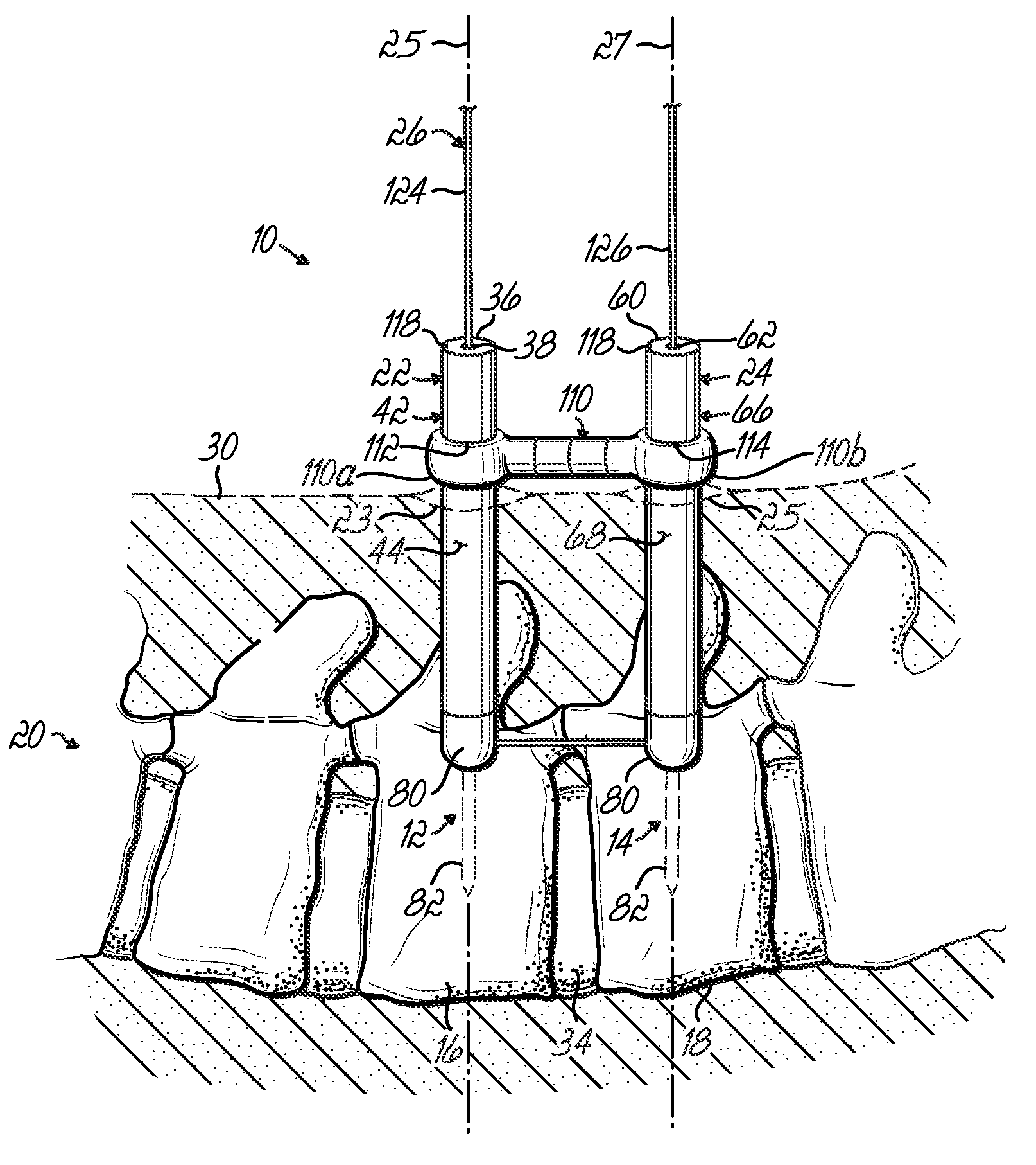
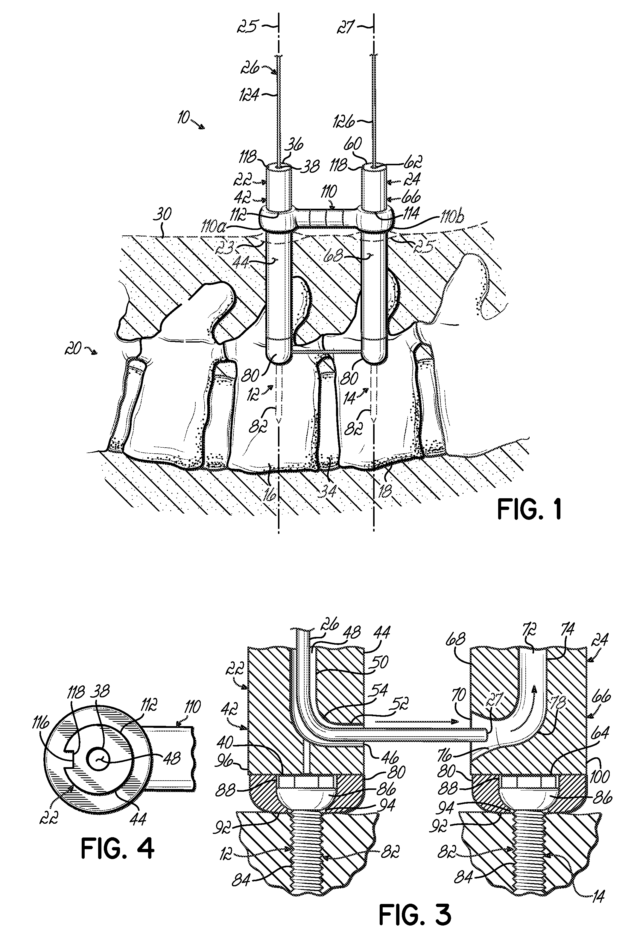
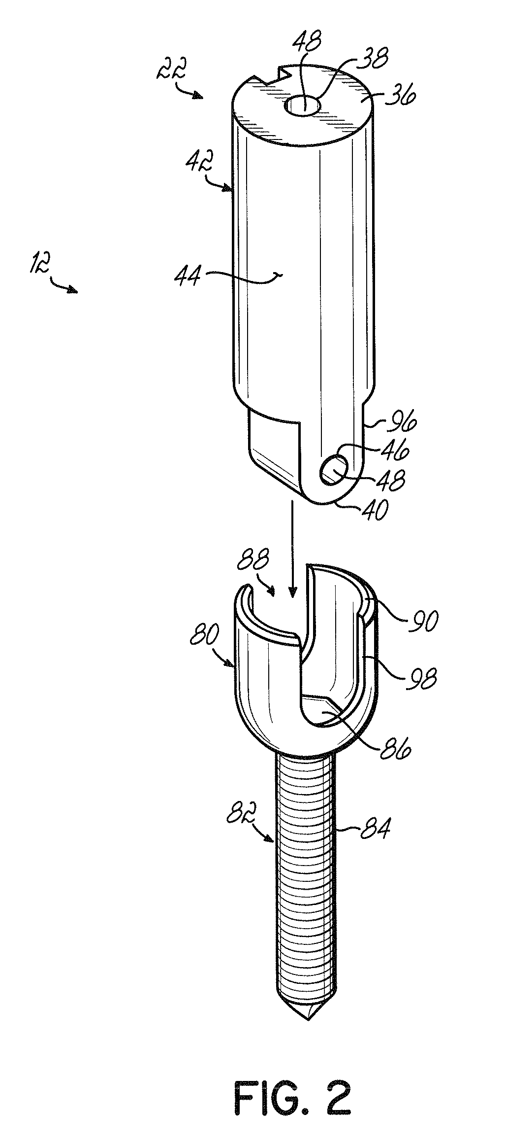
[0021]FIG. 1 shows one embodiment of a minimally invasive surgical system lo according to the invention. The system lo may be used for a variety of surgical procedures, but will described below primarily with reference to spinal surgery procedures. In particular, the system lo will be described with reference to spinal fusion techniques in which first and second anchor members 12, 14 are secured to adjacent vertebrae 16, 18 of a spine 20.

[0022]To this end, the system lo includes first and second docking members 22, 24 configured to be passed through two incisions 23, 25, respectively, to be removably coupled to the first and second anchor members 12, 14 within a body 30 substantially along respective first and second axes 25, 27. The first and second docking members 22, 24 are also configured to facilitate the insertion of a wire member 26, such as a guidewire 26, into the body 30. As will be described in greater detail below, the wire member 26 serves to direct a cross member 32 (F...


PUM


Abstract

A system for installing a cross member between first and second anchor members within a patient's body generally includes first and second docking members configured to be removably coupled to the respective first and second anchor members. Each docking member has a first end with an opening, a second end, and a body extending between the first and second ends. The body includes an outer surface with an opening, and a bore extends from the opening on the first end of the body to the opening on the outer surface. The openings on the outer surface of each docking member are configured to be aligned so that the bore in the first docking member is able to direct a wire member into the bore in the second docking member. A method for minimally invasive surgery using the system is also disclosed.

Description

FIELD OF THE INVENTION[0001]This invention relates generally to surgical systems and methods, and more particularly to a system and method for minimally invasive spinal surgery.BACKGROUND[0002]The spinal column is a highly complex system of bones and connective tissues that provides support for the body and protects the delicate spinal flexible connecting member and nerves. The spinal column includes a series of vertebrae stacked one on top of the other, each vertebral body including an inner or central portion of relatively weak cancellous bone and an outer portion of relatively strong cortical bone. Situated between each vertebral body is an intervertebral disc that cushions and dampens compressive forces experienced by the spinal column. A vertebral canal containing the spinal flexible connecting member and nerves is located behind the vertebral bodies.[0003]There are many types of spinal column disorders including scoliosis (abnormal lateral curvature of the spine), kyphosis (ab...

Claims


Application Information

Patent Timeline
Patent Type & Authority Patents(United States)
IPC IPC(8): A61B17/70
CPCA61B17/7085A61B17/7031A61B17/7032
Inventor HESTAD, HUGH D.
Owner ZIMMER SPINE INC
Why Eureka
Try Eureka