Methods and apparatus for manufacturing and assembling a baghouse bag filter tensioning assembly

a technology of tensioning assembly and bag filter, which is applied in the direction of wound springs, separation processes, transportation and packaging, etc., can solve the problems of reducing the efficiency of fluid flow through the bag filter fabric, increasing the cost of operating and maintaining the filtering system, and requiring sufficient force to collapse the bag filter inward, so as to facilitate the induction of substantially constant spring tension and increase the spring rate. , the effect of increasing the spring ra

Active Publication Date: 2010-01-19
BHA ALTAIR
View PDF19 Cites 6 Cited by
  • Summary
  • Abstract
  • Description
  • Claims
  • Application Information

AI Technical Summary

Benefits of technology

[0007]In one aspect, a method of assembling a baghouse bag filter tensioning assembly is provided. The assembly includes a compressible spring having a progressively increasing spring rate. The spring rate facilitates induction of a substantially constant spring tension over a range of pre-determined operating conditions. The method includes coupling the spring to a bag filter support frame and a bag filter. The method also includes compressing the spring into a pretensioned condition. The method further includes coupling a bag filter to a baghouse floor. The method also includes decompressing the spring such that a tension induced in the bag filter is substantially similar to the spring tension induced over a range of pre-determined operating conditions.
[0008]In another aspect, a compressible spring is provided. The spring includes a plurality of portions that include at least one straight spring portion and at least one conical spring portion. The at least one straight spring portion and the at least one conical spring portion are contiguously formed as a continuous member. The spring includes a progressively increasing spring rate. The spring rate facilitates induction of a substantially constant spring tension within the spring over a range of pre-determined operating conditions. The spring also includes a first open end that includes a first diameter formed at a straight spring portion longitudinal outermost region and a second open end that includes a second diameter formed at a conical spring portion longitudinal outermost region. The first diameter is larger than the second diameter.
[0009]In a further aspect, a baghouse filter system is provided. The system includes a bag filter support frame including a structural support member wherein the member includes at least one bag filter support frame open passage. The system also includes at least one bag filter assembly including a bag filter upper mechanical coupling device, a bag filter lower mechanical coupling device, an external surface, and an interior cavity that includes a fibrous material collection surface. The collection surface collects materials with a plurality of pre-determined dimensions entrained in a fluid. The system further includes a bag filter tensioning assembly including at least one compressible spring and a plurality of coupling devices. The spring is coupled to the bag filter via at least one coupling device. The spring has a plurality of portions that include a straight spring portion and a conical spring portion. The straight spring portion and conical spring portion are contiguously formed as a continuous member with a progressively increasing spring rate. The spring rate facilitates induction of a substantially constant spring tension over a range of pre-determined operating conditions. The spring tension is subsequently induced in the bag filter. The system also includes a plurality of chambers including an inlet plenum, an outlet plenum and a material collection hopper. The system further includes a baghouse floor including at least one bag house floor open passage and at least one bag filter-to-baghouse floor coupling device. The system also includes a reverse fluid flow sub-system.

Problems solved by technology

During extended operation of a bag filtration system in the filtration mode, particulates accumulate on an interior surface of the filter such that “caking” of the particulates occurs on the bag filter interior surface, thereby tending to reduce the efficiency of fluid flow through the bag filter fabric.
Removing the system from service and employing manual labor tends to facilitate an increase in the expense of operating and maintaining the filtering system.
Some known reverse flow cleaning processes may tend to induce sufficient force to collapse bag filters inward.
This condition tends to reduce the effectiveness of the cleaning operation by at least partially collapsing bag filters such that dislodging the caked particulate matter is partially prevented.
However, if the bag filters are stretched too tightly, the extended tension tends to induce a weakening of the fabric structure and the bag filters may wear more quickly.
Also, cycling between filtering mode and cleaning mode induces varying tensions in the fabric and may cause the fabric to stretch.
Varying tensions in the filter bags outside of pre-determined tolerances may increase the number of system outages, manual inspections and subsequent manual re-tensioning of the bag filters.
If left unattended, the stretching of the fabric may eventually result in a failure of the bag filter.
Alternately, if the tension of the bag filters is such that the bag filters are too loose, the bag filters tend to bend or flex such that they rub against one another or against other system components, resulting in bag filter abrasion and possible failure as well as negatively impact cleaning efforts as described above.
However, some of these known spring tensioning assemblies employ springs that induce sufficient tension in the bag filters during filtration operations, yet may not compress readily and thereby may not increase tension sufficiently during cleaning operations to substantially resist the tendency of bag filter collapse.
Also, some known spring tensioning assemblies induce sufficient tension to resist bag filter collapse during cleaning operations, yet may also induce excessive tension during filtration mode operations.

Method used


Image

  • Methods and apparatus for manufacturing and assembling a baghouse bag filter tensioning assembly
  • Methods and apparatus for manufacturing and assembling a baghouse bag filter tensioning assembly
  • Methods and apparatus for manufacturing and assembling a baghouse bag filter tensioning assembly

Examples


Embodiment Construction

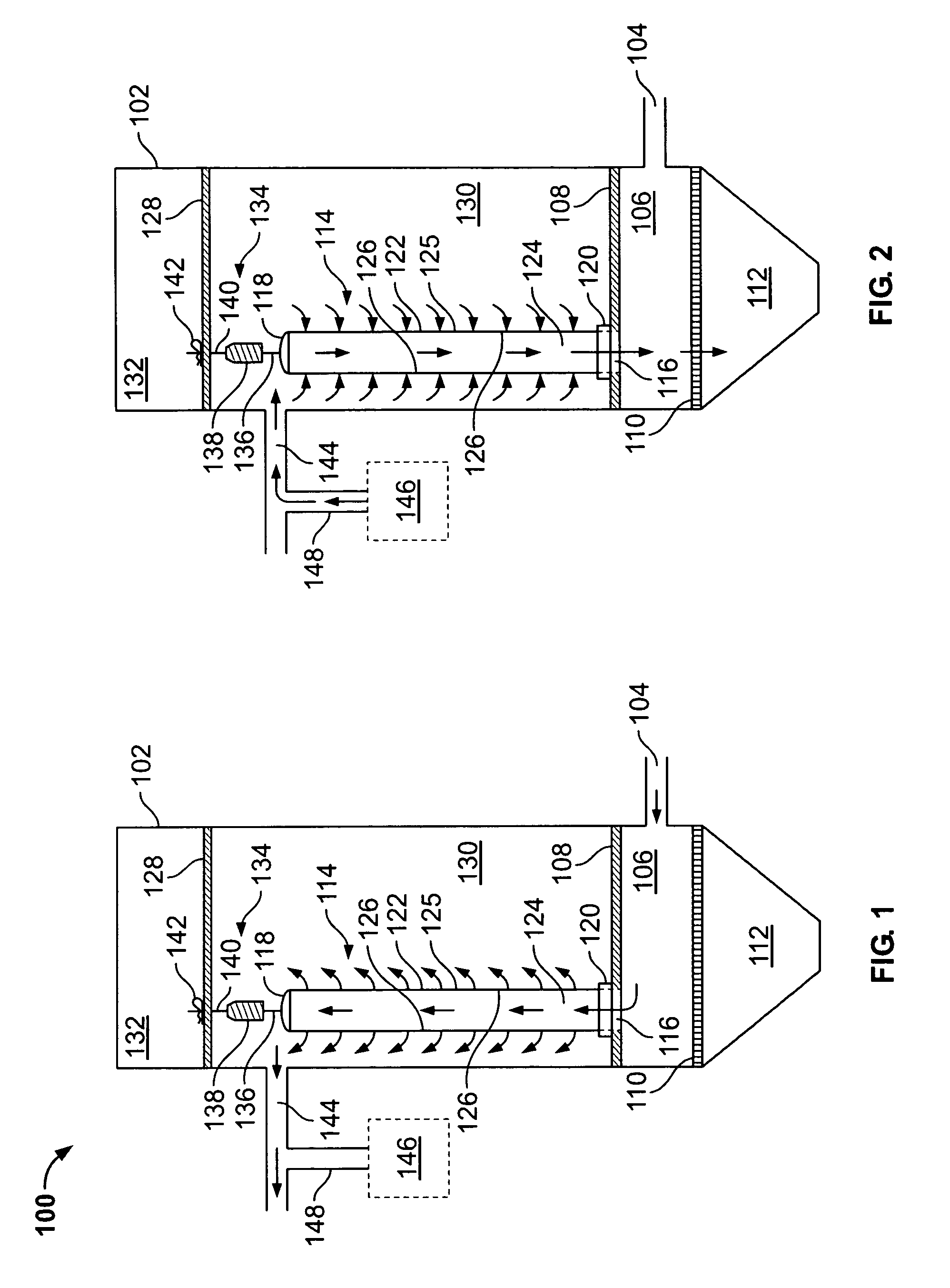
[0020]FIG. 1 is a schematic illustration of an exemplary baghouse filter system 100 in a filtration mode of operation. Flows associated with the fluid flow stream are illustrated by arrows. System 100 includes an enclosure 102, a fluid inlet duct 104, a fluid inlet plenum 106, a baghouse floor 108, a hopper grating 110, a particulate hopper 112, and at least one bag filter assembly 114. Bag filter assembly 114 includes an upper mechanical coupling 118 and a lower mechanical coupling 120. Assembly 114 also includes an elongated fabric filter tube 125 that further includes an external surface region 122, and an interior cavity 124 that includes an interior collection surface 126. System 100 also includes a bag filter support frame 128 that, in conjunction with floor 108 and a portion of enclosure 102, forms outlet plenum 130. Support frame 128 and a portion of enclosure 102 form upper access chamber 132. System 100 further includes a bag filter tensioning assembly 134 that further inc...


PUM

PropertyMeasurementUnit
diameteraaaaaaaaaa
thicknessaaaaaaaaaa
tensionaaaaaaaaaa

Abstract

A method of assembling a baghouse bag filter tensioning assembly is provided. The assembly includes a compressible spring having a progressively increasing spring rate. The spring rate facilitates induction of a substantially constant spring tension over a range of pre-determined operating conditions. The method includes coupling the spring to a bag filter support frame and a bag filter. The method also includes compressing the spring into a pretensioned condition. The method further includes coupling a bag filter to a baghouse floor. The method also includes decompressing the spring such that a tension induced in the bag filter is substantially similar to the spring tension induced over a range of pre-determined operating conditions.

Description

BACKGROUND OF THE INVENTION[0001]This invention relates generally to industrial baghouses and, more particularly, to a tensioning assembly for connecting bag filters to an overhead support.[0002]Industrial and regulatory emphasis on environmental air quality may tend to increase efforts to develop techniques to improve effectiveness and efficiencies of methods and apparatus for separating and removing particulate matter from a fluid flow stream. At least one known technique for particulate removal is fabric filtration. Some known fabric filtration methods include the use of a baghouse and an associated bag filtration system employing bag filters. One fundamental scheme of operation of a bag filtration system is that a fluid that contains entrained particulate matter enters the interior section of a porous bag filter. The fluid transports through the bag filter fabric and exits the external surface of the bag filter. The particulates, depending on their size and chemical constituents...

Claims


Application Information

Patent Timeline
Patent Type & Authority Patents(United States)
IPC IPC(8): B01D46/00F16F1/06
CPCB01D46/0005B01D46/0067B01D46/02B01D46/06B01D2275/203B01D46/70
Inventor DOEHLA, JAMES ROYPEPKA, JOHN V.
Owner BHA ALTAIR
Why Eureka
Try Eureka