Mask and fabrication method thereof and application thereof

a technology applied in the field of phase shift mask and fabrication method, can solve the problems of poor photolithographic yield, affecting the precision of the photoresist pattern formed by using the binary mask for light exposure, and the thickness of the phase shift layer on the mask is not uniform, so as to reduce the complexity of forming the phase shift mask

Active Publication Date: 2010-01-19
AU OPTRONICS CORP
View PDF10 Cites 2 Cited by
  • Summary
  • Abstract
  • Description
  • Claims
  • Application Information

AI Technical Summary

Benefits of technology

[0010]The invention provides mask, which has better uniformity of light transmittance and phase angle.
[0011]The invention provides a fabrication method for the mask, in which a lift-off process is used to accomplish the fabrication of phase shift layer, so that the conventional issue of non-uniform thickness of the layer caused by the etching process for defining the phase shift layer can be prevented.
[0012]The invention provides a fabrication method for the mask, so as to reduce the fabrication cost for the phase shift mask.
[0013]The invention provides a fabrication method for the mask, in which the mask can be used for light exposure and developing on the photoresist layer, and is quite helpful for improving the precision on defining the photoresist pattern, so that yield of the halftone process and the fabrication tolerance can be improved.
[0030]In summary, the method for fabricating the mask in the invention is using the lift-off process, so as to reduce the complexity of forming the phase shift mask. In addition, the convention issue of non-uniform thickness of the phase shift film, due to the non-uniform etching elects, can be reduced.

Problems solved by technology

Even though the binary mask is widely used in semiconductor fabrication, due to the disadvantage of poor precision for this mask, the precision of the photoresist pattern, which is formed by using the binary mask for light exposure, is affected.
Although the phase shift mask can solve the issue of poor resolution, however, due to the fabrication process including the etching process, the etching process has non-uniform etching on the phase shift layer, resulting in the non-uniform thickness for the phase shift layer on the mask.
After the light passes the phase shift layer at the different positions of the mask, the transmittance or the phase angle may be different, resulting in poor yield for the photolithographic process.
Comparing with the conventional binary mask, since it has more fabrication processes, the probability for defects occurring on fabricating the mask is increasing.
This would cause the higher cost for fabricating the mask.

Method used


Image

  • Mask and fabrication method thereof and application thereof
  • Mask and fabrication method thereof and application thereof
  • Mask and fabrication method thereof and application thereof

Examples


Embodiment Construction

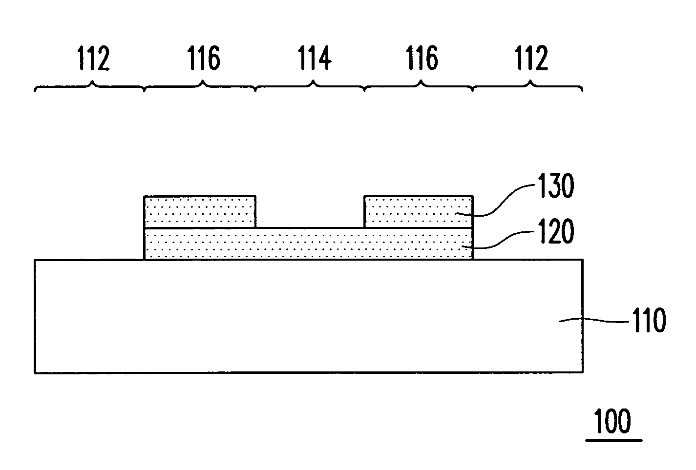
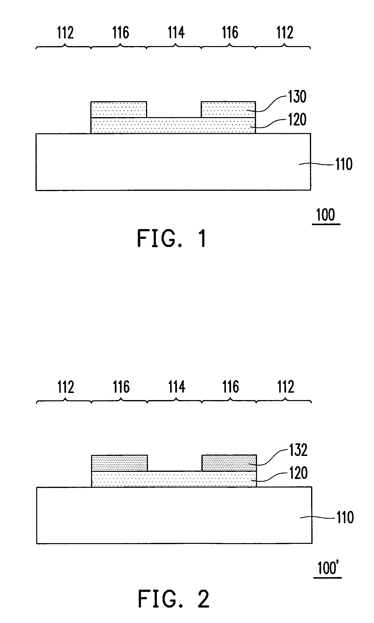
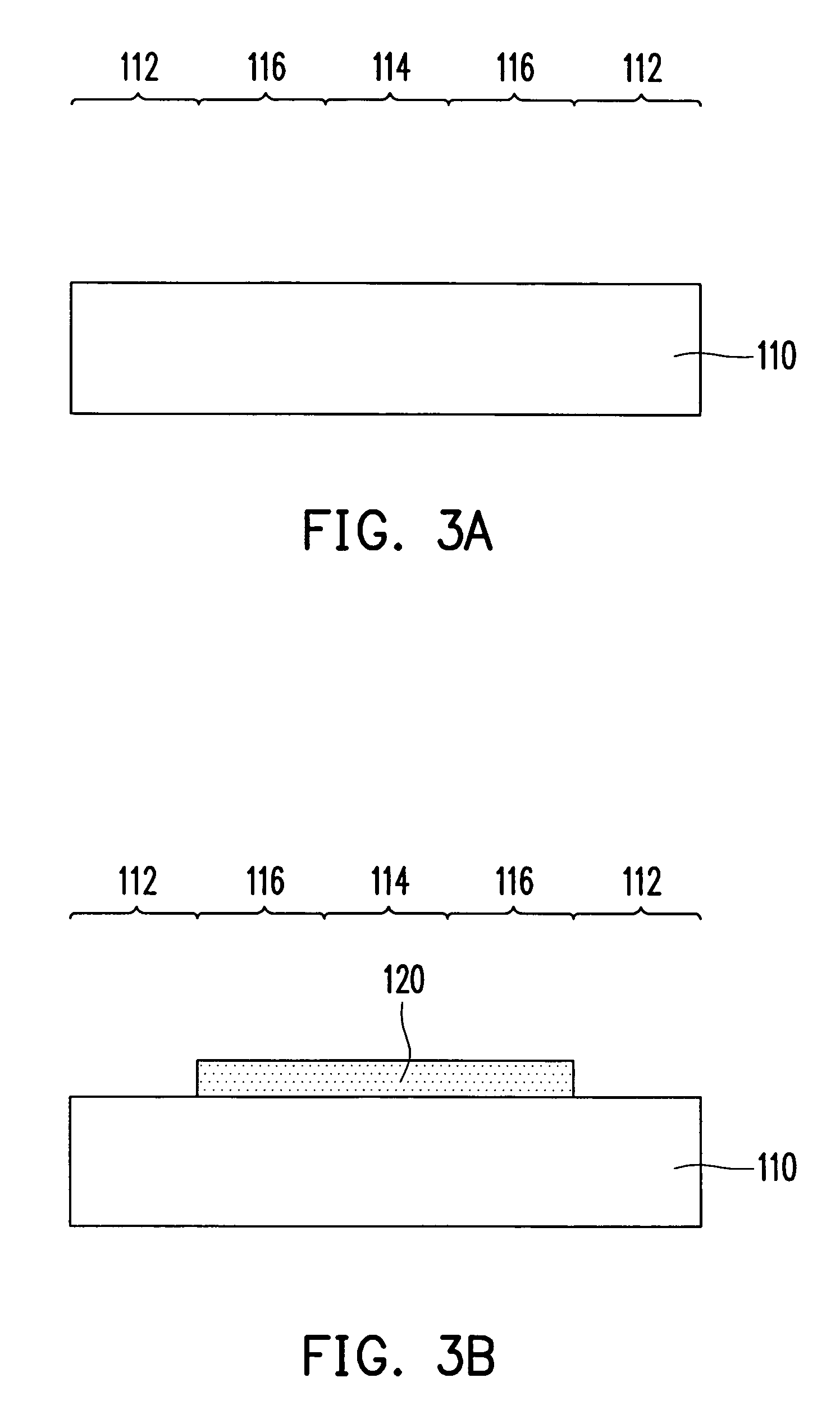
[0040]FIG. 1 is a cross-sectional view, schematically illustrating a mask, according to an embodiment of the invention. In FIG. 1, the mask 100 of the invention mainly includes a transparent substrate 110, a semi-transparent layer 120, and a film layer 130. The transparent substrate 110 formed from, for example, quartz or other transparent material, is having a first region 112, a second region 114, and a third region 116. The semi-transparent layer 120 covers over the second region 114 and the third region 116 of the transparent substrate 110, and the first region 12 is exposed. The semi-transparent layer 120 is formed from, for example, semi-transparent material. The film layer 130 covers the semi-transparent layer 120 at the third region 116. Since the third region 116 on the transparent substrate 110 is disposed with the semi-transparent layer 120 and the film layer 130, and the second region 114 is only disposed with the semi-transparent layer 120, the light transmittance for t...


PUM

PropertyMeasurementUnit
semi-transparentaaaaaaaaaa
transparentaaaaaaaaaa
shieldingaaaaaaaaaa

Abstract

A mask including a transparent substrate, a semi-transparent layer and a film layer is provided. The transparent substrate at least has a first region, a second region and a third region. The semi-transparent layer covers the second region and the third region of the transparent substrate and exposes the first region. The film layer covers the halftone layer disposed at the third region, to make the transmittance of the third region lower than that of the second region. The halftone layer and the film can be made of phase shift layers, to form a phase shift mask. Besides, several fabrication methods of the mask are also disclosed to form the above-mentioned mask.

Description

CROSS-REFERENCE TO RELATED APPLICATION[0001]This application claims the priority benefit of Taiwan application serial no. 94147541, filed on Dec. 30, 2005. All disclosure of the Taiwan application is incorporated herein by reference.BACKGROUND OF THE INVENTION[0002]1. Field of Invention[0003]The present invention relates to a mask and fabrication method thereof and its application. More particularly, the present invention relates to a phase shift mask, PSM as well as its fabrication method and application.[0004]2. Description of Related Art[0005]The fabrication method of the conventional mask includes first providing a quartz substrate and a metal layer is formed on the quartz substrate. After then, a photoresist layer is formed over the quarts substrate and the metal layer. By performing light exposure and developing at the specific region, a portion of the photoresist layer is removed, so as to expose a portion of the metal layer, corresponding to the removed portion of the photor...

Claims


Application Information

Patent Timeline
Patent Type & Authority Patents(United States)
IPC IPC(8): G03F1/00
CPCG03F1/32G03F1/54G03F1/50
Inventor TUNG, CHUN-HAO
Owner AU OPTRONICS CORP
Why Eureka
Try Eureka