Wavelength calibration method and wavelength calibration apparatus

a wavelength calibration and wavelength technology, applied in the direction of optical radiation measurement, instruments, spectrometry/spectrophotometry/monochromators, etc., can solve the problems of measurement wavelength error, interference of emitted light, ripple in wavelength band intensity of emitted light, etc., to achieve high-quality wavelength calibration

Active Publication Date: 2010-01-19
YOKOGAWA ELECTRIC CORP
View PDF5 Cites 24 Cited by
  • Summary
  • Abstract
  • Description
  • Claims
  • Application Information

AI Technical Summary

Benefits of technology

[0014]It is a further object of the present invention to provide a wavelength calibration method free from any causes for errors in wavelength measurement when a light emitting diode is used as a light source.
[0015]It is a still further object of the present invention to provide a wavelength calibration method that is capable of realizing a highly accurate wavelength calibration.
[0018]It is another object of the present invention to provide a wavelength calibration apparatus free from any causes for errors in wavelength measurement when a light emitting diode is used as a light source.
[0019]It is still another object of the present invention to provide a wavelength calibration apparatus that is capable of realizing a highly accurate wavelength calibration.

Problems solved by technology

If the absorption wavelengths are different from the particular wavelengths, this means that the measured wavelength has an error.
The light emitting diode may cause an interference of the emitted light in the semiconductor chip.
The interference of the emitted light may cause a ripple in intensity of the emitted light in the wavelength band.
The ripple may cause errors of the absorption wavelengths.
The overall unevenness of the light intensity distribution may cause further errors of the absorption wavelengths.

Method used


Image

  • Wavelength calibration method and wavelength calibration apparatus
  • Wavelength calibration method and wavelength calibration apparatus
  • Wavelength calibration method and wavelength calibration apparatus

Examples


Embodiment Construction

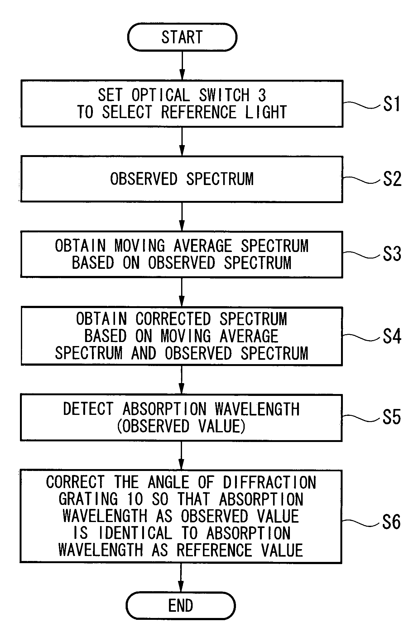
[0030]In accordance with a first aspect of the present invention, a wavelength calibration method may include, but is not limited to, the following processes. An observed spectrum of a light that has a wavelength band may be obtained, wherein the light has at least an attenuated wavelength component that corresponds to at least a predetermined absorption wavelength that is included in the wavelength band. A corrected spectrum may be obtained from the observed spectrum, wherein the corrected spectrum has reduced dependencies upon the full width at half maximum of an emission band of the light and upon an intensity ripple period of the light. A wavelength calibration may be performed with reference to the corrected spectrum. The reduction of the dependencies upon the full width at half maximum of an emission band of the light and upon an intensity ripple period of the light may improve the accuracy in wavelength calibration.

[0031]In some cases, the corrected spectrum may be substantia...


PUM


Abstract

In a wavelength calibration method, an observed spectrum of a light that has a wavelength band is obtained, wherein the light has at least an attenuated wavelength component that corresponds to at least a predetermined absorption wavelength that is included in the wavelength band. A corrected spectrum is then obtained from the observed spectrum, wherein the corrected spectrum has reduced dependencies upon the full width at half maximum of an emission band of the light and upon an intensity ripple period of the light.

Description

BACKGROUND OF THE INVENTION[0001]1. Field of the Invention[0002]The present invention generally relates to a wavelength calibration method and a wavelength calibration apparatus.[0003]Priority is claimed on Japanese Patent Application No. 2006-041082, filed Feb. 17, 2006, the content of which is incorporated herein by reference.[0004]2. Description of the Related Art[0005]All patents, patent applications, patent publications, scientific articles, and the like, which will hereinafter be cited or identified in the present application, will hereby be incorporated by reference in their entirety in order to describe more fully the state of the art to which the present invention pertains.[0006]Japanese Unexamined Patent Application, First Publication, No. 2000-283841 discloses a conventional wavelength calibration technique to be used in an optical spectrum analyzer. This conventional wavelength calibration technique will be described as follows. A light emitting diode is performed as a r...

Claims


Application Information

Patent Timeline
Patent Type & Authority Patents(United States)
IPC IPC(8): G01J3/26
CPCG01J3/02G01J3/0297G01J3/08G01J3/10G01J3/1804G01J3/28G01N21/274G01J2003/2873
Inventor YAMAMOTO, TOSHIKAZU
Owner YOKOGAWA ELECTRIC CORP
Why Eureka
Try Eureka