Self limiting zero voltage switching power conversion networks

a zero-voltage switching and network technology, applied in the field of electronic power conversion circuits, can solve problems such as potential electromagnetic interference (emi), circuits that cannot achieve zero-voltage switching, etc., and achieve the effects of limiting the voltage stress of the power converter's switches, and reducing the loss of first-order drain circuit switching losses

Inactive Publication Date: 2010-01-19
WITTENBREDER JR ERNEST HENRY
View PDF4 Cites 3 Cited by
  • Summary
  • Abstract
  • Description
  • Claims
  • Application Information

AI Technical Summary

Benefits of technology

[0005]An object of the subject invention is to reveal new beneficial circuit topologies for applications with limited line voltage range and either very large or very small step up or step down ratios.
[0006]Another object of the subject invention is to reveal new beneficial circuit topologies with zero voltage switching for elimination of first order drain circuit switching losses.
[0007]Another object of the subject in...

Problems solved by technology

The FIG. 1 circuit does not achieve zero voltage switching unless the coupled inductor has inherent to it a large amount of leakage inductance....

Method used


Image

  • Self limiting zero voltage switching power conversion networks
  • Self limiting zero voltage switching power conversion networks
  • Self limiting zero voltage switching power conversion networks

Examples


Embodiment Construction

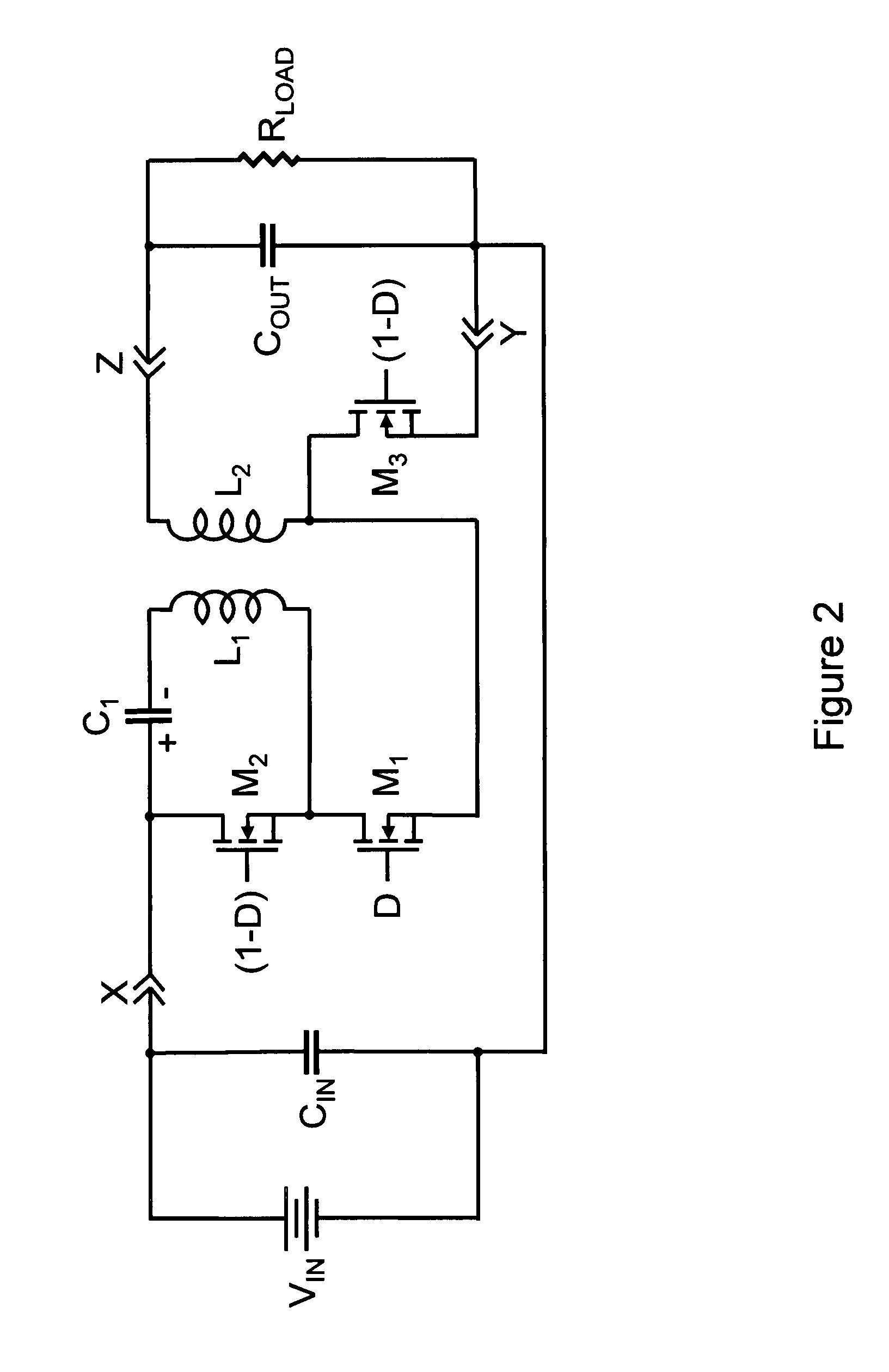
[0032]FIG. 2 illustrates a capacitor coupled buck converter according to the subject invention. In FIG. 2 a first terminal of a source of dc voltage and power, VIN, is connected to a first terminal of a capacitor, CIN, and a first terminal, X, of a power conversion network. A second terminal of VIN is connected to a second terminal of capacitor, CIN, a second terminal, Y, of the power conversion network, a first terminal of a capacitor, COUT, and a first terminal of a load, RLOAD. The terminal, X, of the power conversion network is connected to a first terminal of a capacitor, C1, and a first terminal of a switch, M2. A second terminal of the capacitor, C1, is connected to a first terminal of an inductor, L1. A second terminal of inductor, L1, is connected to a second terminal of the switch M2 and to the first terminal of a switch, M1. A second terminal of switch M1 is connected to a first terminal of an inductor L2 and to a first terminal of a switch M3. A second terminal of switch...


PUM


Abstract

The subject invention reveals a new three terminal canonical cell for non-isolated power conversion. The canonical cell achieves reduced semiconductor component stresses for applications with limited line voltage range for small step up and step down ratios or for large step up and step down ratios. Some of the canonical cells can be used to form buck, boost, and buck boost converters. The new canonical cell achieves zero voltage switching over a broad range of line and load voltages and is self limiting without the addition of additional components to sense and respond to over load current.

Description

BACKGROUND OF THE INVENTION[0001]1. Field of the Invention[0002]The subject invention generally pertains to electronic power conversion circuits, and, more specifically, to high frequency, switched mode electronic power converters. The subject matter relates to new non-isolated power conversion networks which provide high efficiency power conversion under special conditions where more conventional power conversion networks do not work as well.[0003]2. Description of Related Art[0004]The solution to the problem of converting power where the input to output or output to input voltage ratio is either very small or very large has traditionally relied upon tapped inductor power converters. New tapped inductor power conversion networks have been introduced that achieve reduced semiconductor and magnetic circuit element component stresses. An example of a circuit that achieves improved efficiency over the known alternatives for large input to output step down ratios is illustrated in FIG. ...

Claims


Application Information

Patent Timeline
IPC IPC(8): H02M3/335
CPCH02M3/33569H02M3/01H02M3/158
Inventor WITTENBREDER, JR., ERNEST HENRY
Owner WITTENBREDER JR ERNEST HENRY
Why Eureka
Try Eureka