

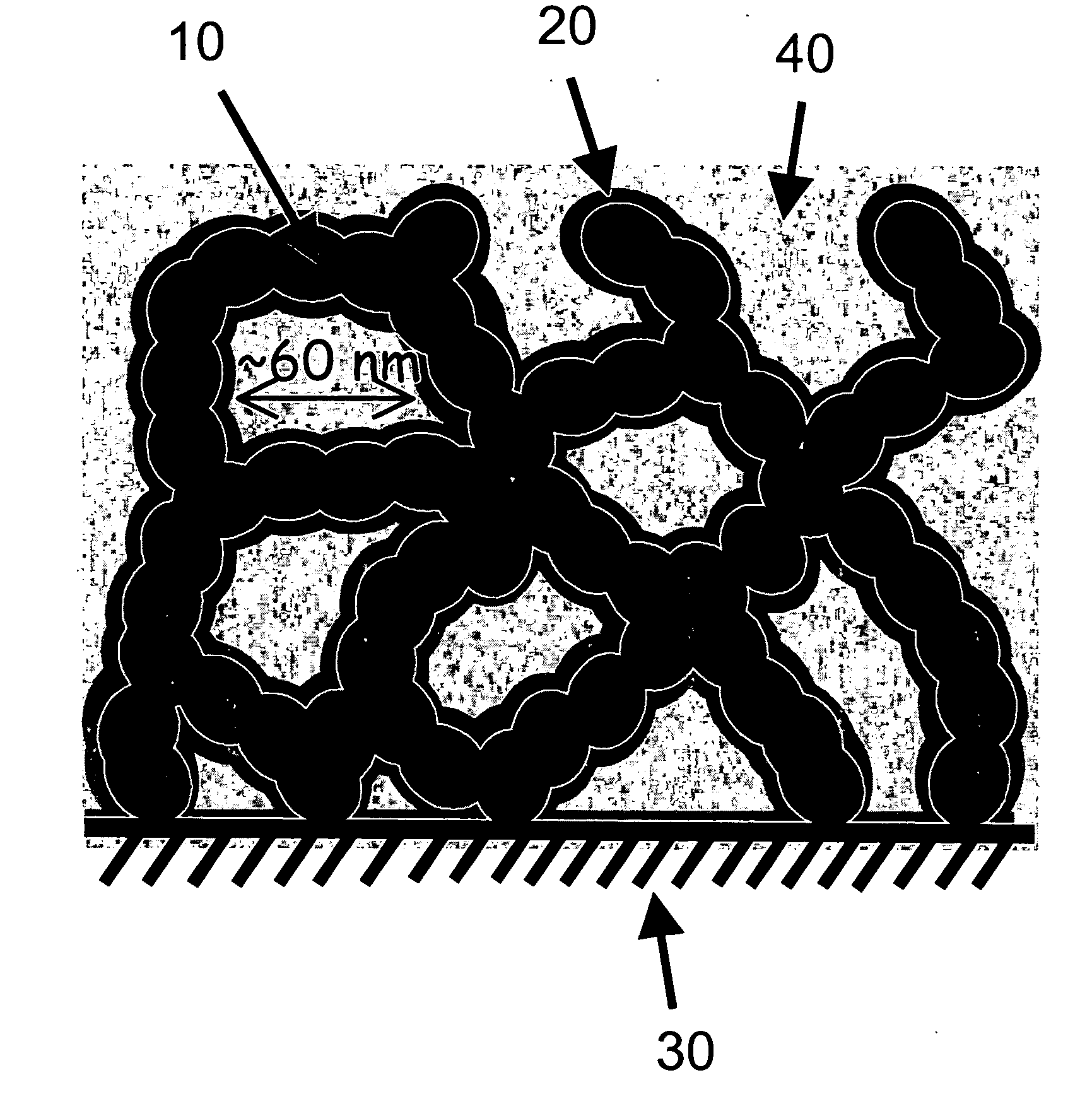
Carbon nanoarchitectures with ultrathin, conformal polymer coatings for electrochemical capacitors
a carbon nano-architecture and conformal polymer technology, applied in the field of composites, can solve the problems of limited application of ruosub>2 /sub>, conductivity less than 1 s/cm compared to carbon-based capacitors, and conductivity less than 1 s/cm
- Summary
- Abstract
- Description
- Claims
- Application Information
AI Technical Summary
Benefits of technology
Problems solved by technology
Method used
Image


Examples
example 1
[0027] Electropolymerization—Carbon aerogels were prepared according to established procedures (V. Bock et al., J. Non-Cryst. Solids, 225, 69 (1998)). Monolithic pieces of carbon aerogel (2-4 mg) were incorporated into a stainless-steel basket electrode, which provided for electrical contact between the aerogel and a potentiostat / galvanostat. This assembly was equilibrated in a hydration chamber for 24 hours to wet the carbon surfaces, then immersed in an initial electrolyte and evacuated for 2 hr. This procedure was used to efficiently infiltrate the porous carbon structure with electrolyte. The equilibrated electrode assembly was immersed in an electrolyte containing 20 mM oxidizable monomer, such as o-methoxyaniline, 0.2 M Na2SO4, and 50 mM citrate buffer. Polymerization of the monomer was initiated using a number of electrochemical techniques including voltammetric, potentiostatic, galvanostatic, potential-pulse, and current-pulse methods. For the class of aniline-based monomers...
example 2
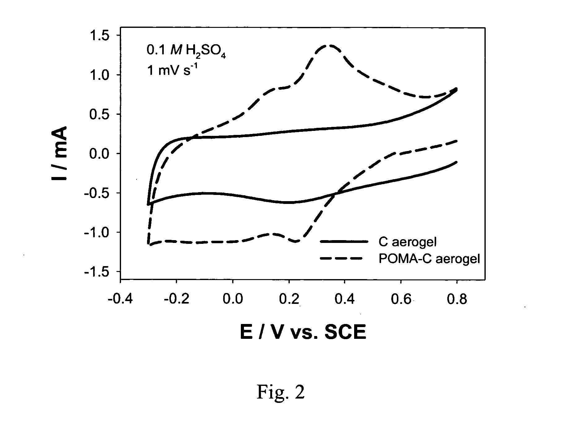
[0028] Electrochemical characterization—Following the electropolymerization step, the electrode assembly was transferred to an aqueous acid electrolyte, typically 0.1 M H2SO4, for electrochemical characterization. Under these acidic conditions the ultrathin polymer coating became electroactive. The overall electrochemical capacitance of the hybrid structure was increased by the pseudocapacitance of the activated polymer component. Galvanostatic (constant-current) charge-discharge cycling was used to assess the capacitance of the electrode as a function of the current load and the number of cycles.
[0029]FIG. 2 shows a comparison of cyclic voltammograms of a carbon aerogel and a poly(o-methoxyaniline)-coated carbon aerogel. This comparison shows the presence of the peaks for the oxidation and reduction of the POMA coating at the carbon aerogel electrode.
[0030] With a carbon aerogel coated with poly(o-methoxyaniline), POMA, the gravimetric capacitance was increased ˜35% for a current...
PUM
| Property | Measurement | Unit |
|---|---|---|
| diameter | aaaaa | aaaaa |
| thickness | aaaaa | aaaaa |
| thick | aaaaa | aaaaa |
Abstract
Description
Claims
Application Information