X-ray source

a source and x-ray technology, applied in the field of x-ray sources, can solve the problems of divergence action, inability to judge the presence or absence of defects, and inability to obtain the contrast of an exposure image, so as to reduce the effect of divergence action

Inactive Publication Date: 2010-01-19
THE UNIV OF TOKYO +1
View PDF5 Cites 37 Cited by
  • Summary
  • Abstract
  • Description
  • Claims
  • Application Information

AI Technical Summary

Benefits of technology

[0013]The present invention has been made in view of the circumstance described above. It is an object of the present invention to provide an X-ray source, which is capable of radiating X-rays with low energy and ensuing focus size performance equal to or more excellent than that of a current micro-focus X-ray source with high energy.
[0015]According to the present invention, there can be provided an X-ray source, which is configured to accept a deceleration effect immediately before electron beams converged by means of an electro-optical system are incident to a transmission target with a ground potential, so that the electron beams have energy that is several times of a final setting until they have passed through the electro-optical system, making it possible to reduce a divergence action that is exerted by a spatial electric charge effect, and in which color aberration is proportional to energy of the electron beams in a variety of aberrations of the electro-optical system as it is, thus employing a configuration of achieving deceleration after the electron beams have passed through the electro-optical system, thereby reducing aberration in proportion to the degree of deceleration, enabling concurrent reduction of a focus size, and therefore, radiating X-rays with low energy at a microscopic focus.

Problems solved by technology

This is because, when transmission exposure of an inspection site in a microscopic area is carried out, if the energy of X-rays to be used is too high, the contrast of an exposure image cannot be obtained, making it impossible to judge the presence or absence of a defect.
However, in the case where it becomes possible to radiate X-rays with low energy with a conventional configuration of a micro-focus X-ray source kept unchanged, this caused the following problems to be solved.
One problem is that a divergence action occurs due to a spatial electric charge effect at the time of crossover of electron beams in an electro-optical system.
The other problem is that, with lower energy, the blurring quantity of a focus on an image forming face increases under the strong influence of the magnetic field of the electro-optical system or color aberration of an electric field lens.
The physical constraints in achieving radiation intensity (dosage) of X-rays with low energy primarily include two problems described below.
One of these problems is that it is disadvantageous to apply electron beams with low energy from the viewpoint of increase in dosage because the radiation quantity of controlled X-rays is substantially proportional to energy of excitation electrons.
The other problem is that it becomes difficult to achieve radiation intensity of X-rays with low energy due to the attenuation (absorption) effect associated with transparent target.
Therefore, it is impossible to maintain the initial microscopic focus size merely by reducing and operating a drive voltage of a current micro-focus X-ray source with high energy.
In addition, it is difficult to include the limit of an achievable focus size in a satisfactory range merely by making a design change so as to cope with low voltage driving with a configuration thereof kept unchanged.

Method used


Image

  • X-ray source
  • X-ray source
  • X-ray source

Examples


first embodiment

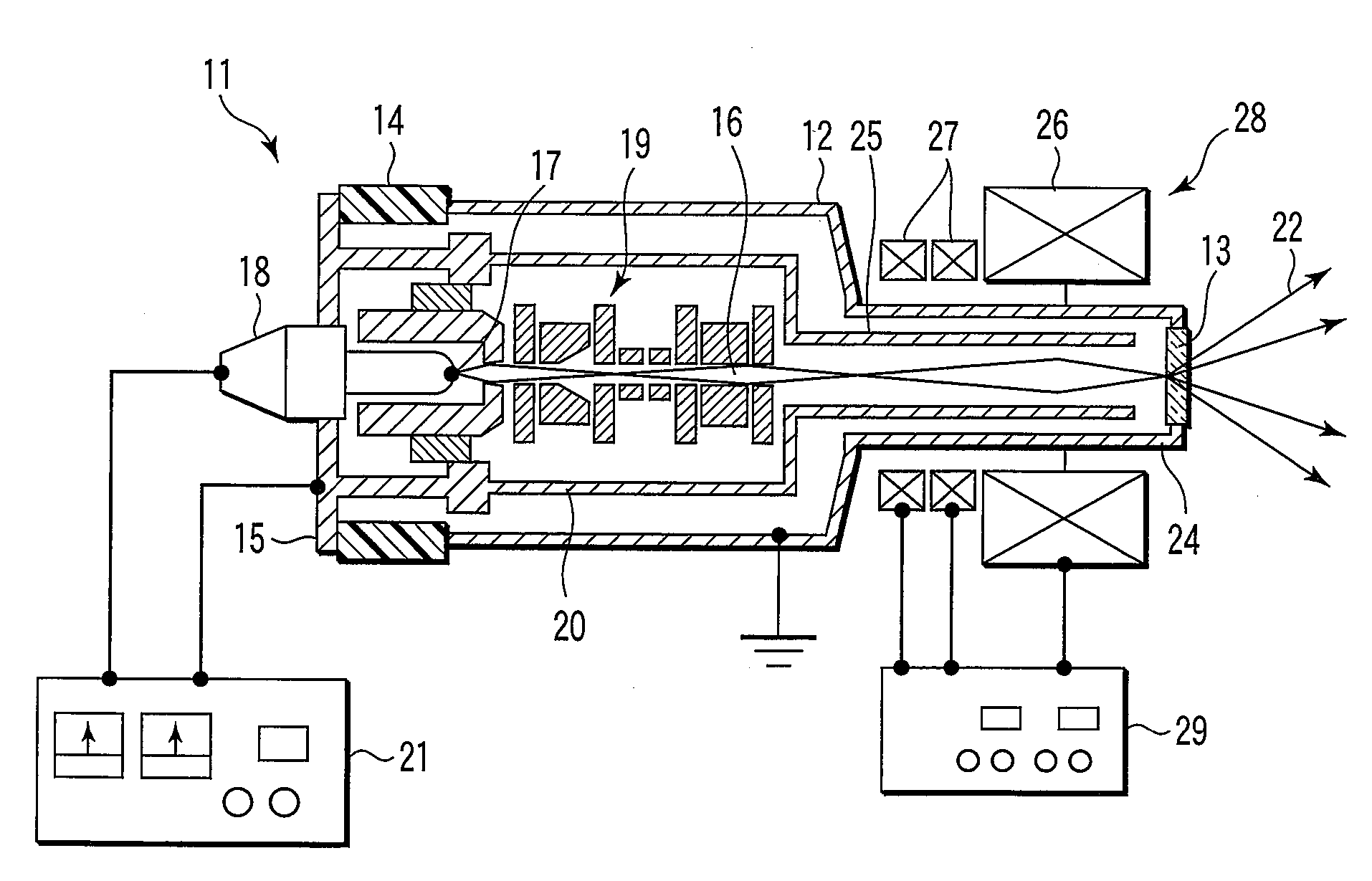
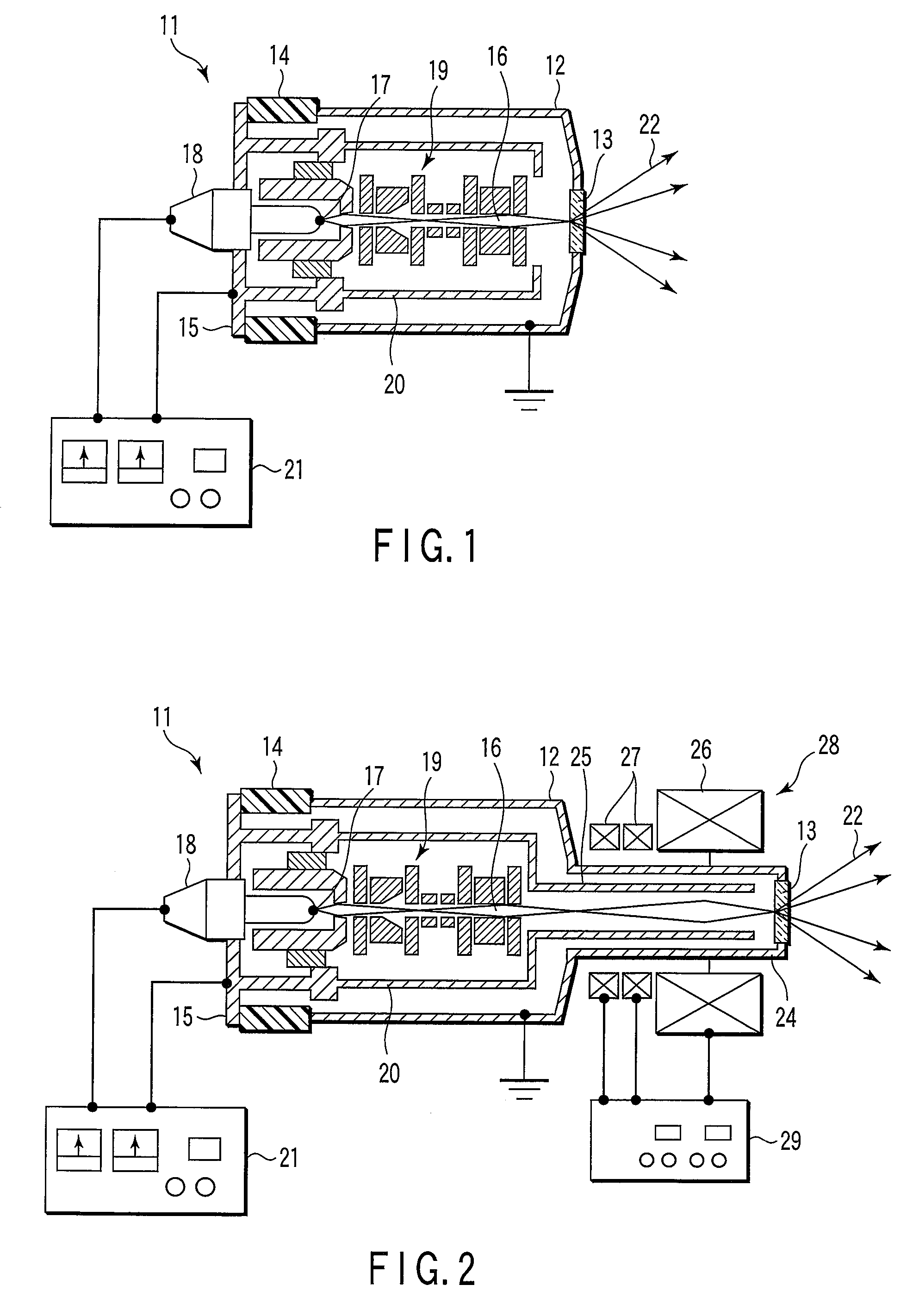
[0027]FIG. 1 shows an X-ray source 11.

[0028]The X-ray source 11 has a vacuum container 12, an inside of which is maintained in vacuum, and a transmission target 13 compatible with an X-ray radiation window for externally radiating X-rays is arranged at one end of this vacuum container 12.

[0029]At the other end of the vacuum container 12, a support member 15 is arranged while an insulation cylinder 14 serving as an insulation member is interposed. On the support member 15, there are arranged an electron gun 18 having an electron source 17 for generating electron beams 16 toward the transmission target 13, and an electrostatic electro-optical system 19 having equipment such as an electrostatic lens (gun lens), for example, for converging, deflecting, and further, aberration-correcting the electron beams 16 located in the vacuum container 12 and generated from the electron source 17 to make them incident to the transmission target 13. On the support member 15, a cover portion 20 is for...

second embodiment

[0042]Next, an X-ray source 11 is shown in FIG. 2.

[0043]In the X-ray source 11, a cylinder portion 24 in which a transmission target 13 is arranged at a tip end is formed at one end of a vacuum container 12, and a sleeve 25 through which electron beams 16 converged by means of an electro-optical system 19 and incident to the transmission target 13 pass, is arranged inside this cylinder portion 24. The sleeve 25 is formed at a coverage portion of a support member and is electrically insulated from the vacuum container 12, and then, a positive voltage is applied from a drive power source 21.

[0044]A magnetic field type electro-optical system 28 having a magnetic field lens (objective lens) 26 and a magnetic field type multi-poles 27 is arranged outside the cylinder portion 24. The magnetic field lens 26 and the multi-poles 27 are operable to have the same ground potential as that of the vacuum container 12 or the transmission target 13, and are connected with a control power source 29 ...


PUM


Abstract

A transmission target of a vacuum container is operable to have a ground potential and an electro-optical system is floated at a positive potential in the vacuum container. An electron beam, which is converged by means of the electro-optical system, is decelerated immediately before the electron beam is incident to the transmission target. The electron beam has energy that is several times of the final set value until the electron beam passes through the electro-optical system, and a divergence action exerted by a spatial electric charge effect is reduced. Color aberration of the electro-optical system is proportional to energy of the electron beam. Thus, if the electron beam is decelerated after the electron beam has passed through the electro-optical system, aberration is reduced in proportion to the degree of deceleration, making it possible to concurrently reduce a focus size.

Description

CROSS-REFERENCE TO RELATED APPLICATIONS[0001]This application is based upon and claims the benefit of priority from prior Japanese Patent Application No. 2006-326831, filed Dec. 4, 2006, the entire contents of which are incorporated herein by reference.BACKGROUND OF THE INVENTION[0002]1. Field of the Invention[0003]The present invention relates to an X-ray source for radiating X-rays with low energy at a microscopic focus.[0004]2. Description of the Related Art[0005]A general X-ray source having a microscopic focus has already been produced as a micro-focus X-ray source, and is widely used in equipment such as a nondestructive inspection apparatus for inspecting a microscopic area of a target at a high resolution. This X-ray source employs a configuration in which electron beams radiated from an electron source are converged by means of an electro-optical system such as an electric field or magnetic field lens, a focus is provided in a small area that is equal to or smaller than the...

Claims


Application Information

Patent Timeline
Patent Type & Authority Patents(United States)
IPC IPC(8): H01J35/14
CPCH01J35/08H01J35/14H01J2235/186H01J2235/087H01J35/116H01J35/186H01J35/147H01J2235/081
Inventor AOKI, NOBUTADAKAKUTANI, AKIKOSUGAWARA, TSUYOSHIMIYOSHI, MOTOSUKE
Owner THE UNIV OF TOKYO
Why Eureka
Try Eureka