

Early fouling detection
a technology of early fouling and detection, applied in the field of early fouling detection, can solve the problems of time-consuming and expensive process of removing the relatively thick fouling layer 102
- Summary
- Abstract
- Description
- Claims
- Application Information
AI Technical Summary
Problems solved by technology
Method used
Image

Examples
Embodiment Construction
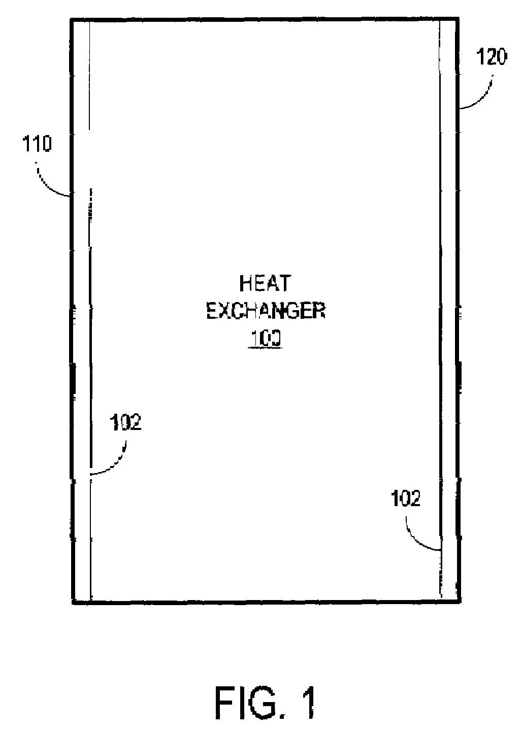
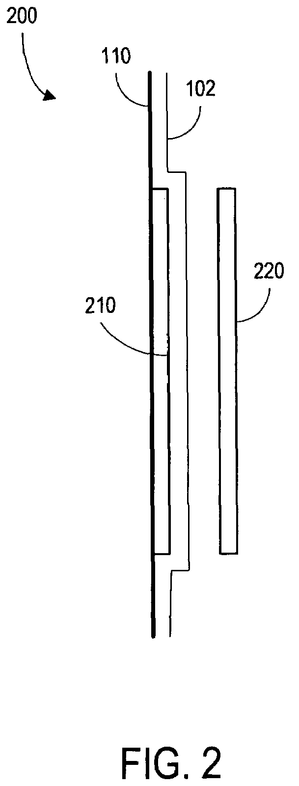
[0019]FIG. 2 is a side view of a system 200 in accordance with an exemplary embodiment of the invention. In particular, the system 200 includes a first capacitive element 210 associated with a surface 110 where a fouling layer 102 is to be detected. The surface 110 may, for example, be an internal surface of a heat exchanger. Note, however, that the surface 110 could instead be associated with any other types of devices that use a liquid, such as a fractionation unit or a process / water system.
[0020]The first capacitive element 210 might comprise, for example, a first conducting plate mounted onto and parallel to the surface 110. Note that a bonding or insulating layer (not illustrated in FIG. 2) might be provided between the surface 110 and the first capacitive element 210. The system 200 further includes a second capacitive element 220, such as a second conducting plate mounted substantially parallel and proximate to the first capacitive element 210.
[0021]As the fouling layer 102 g...
PUM
 Abstract
Description
Claims
Application Information