Control system, electronic device and image forming apparatus

a technology of electronic devices and control systems, applied in the direction of electrical apparatus construction details, power supply for data processing, instruments, etc., can solve the problems of high current consumption, low current consumption of usb devices, and the inability of devices with high current consumption to be connected electrically, so as to reduce situations, reduce current supply, and reduce the effect of situations

Inactive Publication Date: 2010-01-26
SHARP KK
View PDF25 Cites 10 Cited by
  • Summary
  • Abstract
  • Description
  • Claims
  • Application Information

AI Technical Summary

Benefits of technology

[0016]The control system according to the present invention is characterized in that said controller is further capable of performing operations of judging whether another external device is connected to said hub when the judgment result notified from said newly connected external device is that said newly connected external device is inoperable and when it is judged that another external device is connected, reducing current supply to said another external device.
[0045]According to the present invention, in the case that the result of the judgment notified from the newly connected external device is that the newly connected external device is inoperable, the electronic device notifies information saying that current should be supplied to the hub. Hence, in the case that the current is supplied to the hub, the current to be supplied to the newly connected external device can be obtained securely, and it is possible to reduce situations in which the external device cannot be used owing to insufficient supply current.

Problems solved by technology

Because the current consumption of a USB device is generally low, multiple USB devices are frequently operated by only the current supplied from the host, and even when a USB hub is used, no power supply is connected to the USB hub.
However, in the case that a USB device having a high current consumption is connected, problems occur.
For example, overcurrent protection is activated inside the USB port or the USB hub, and the USB device having the high current consumption cannot be connected electrically; or the operating voltage of the USB hub is lowered, and the operation of the USB hub itself and the operation of the USB device connected to the USB hub become unstable or impossible.
In other words, although the maximum current that can be supplied is 500 mA, in the case that a large capacity device is connected, a large current is supplied to the device, and the above-mentioned problems will occur.
As a result, there is a fear of adversely affecting the devices having been connected to the same USB hub.

Method used


Image

  • Control system, electronic device and image forming apparatus
  • Control system, electronic device and image forming apparatus
  • Control system, electronic device and image forming apparatus

Examples


embodiment 1

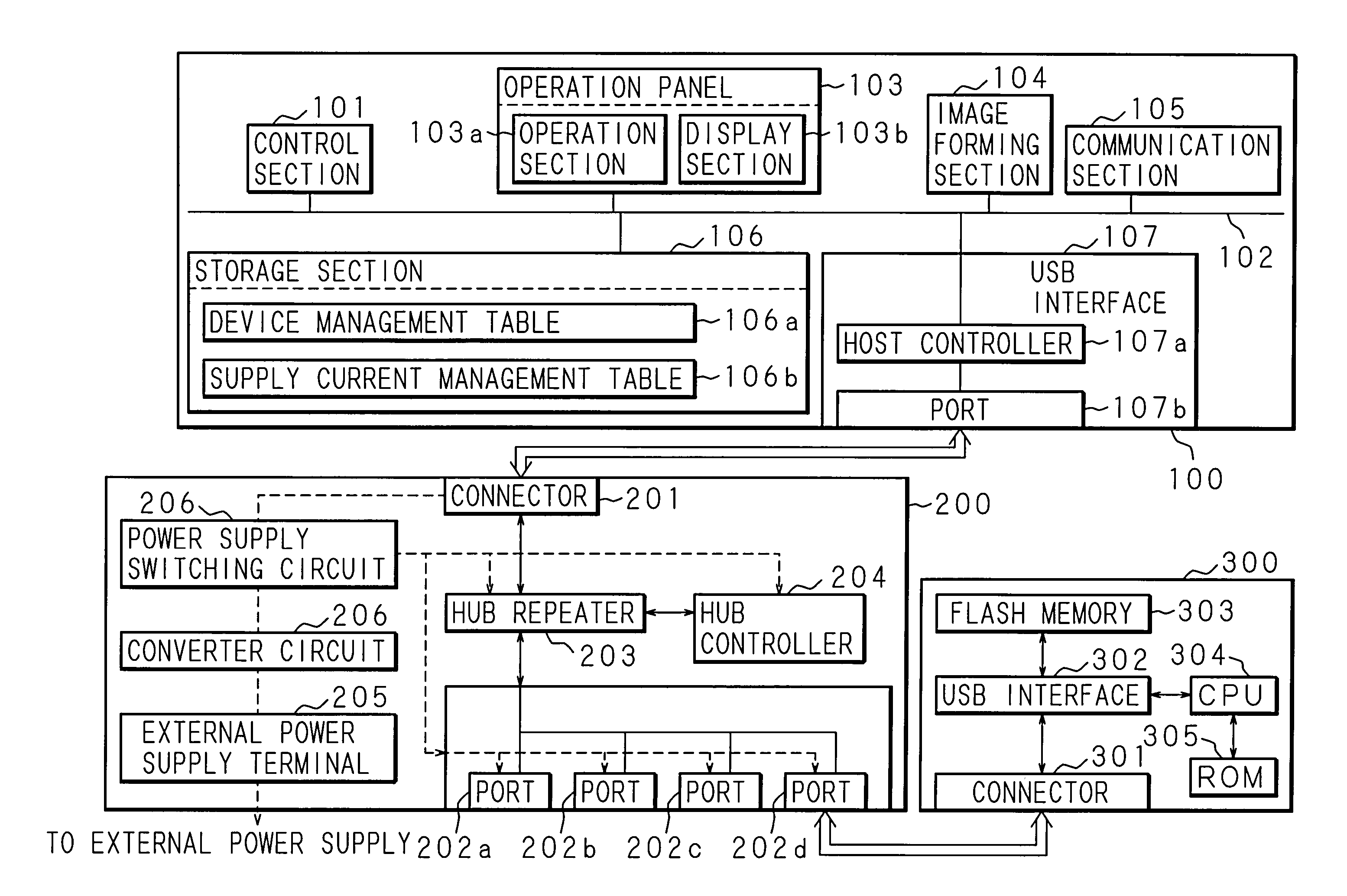
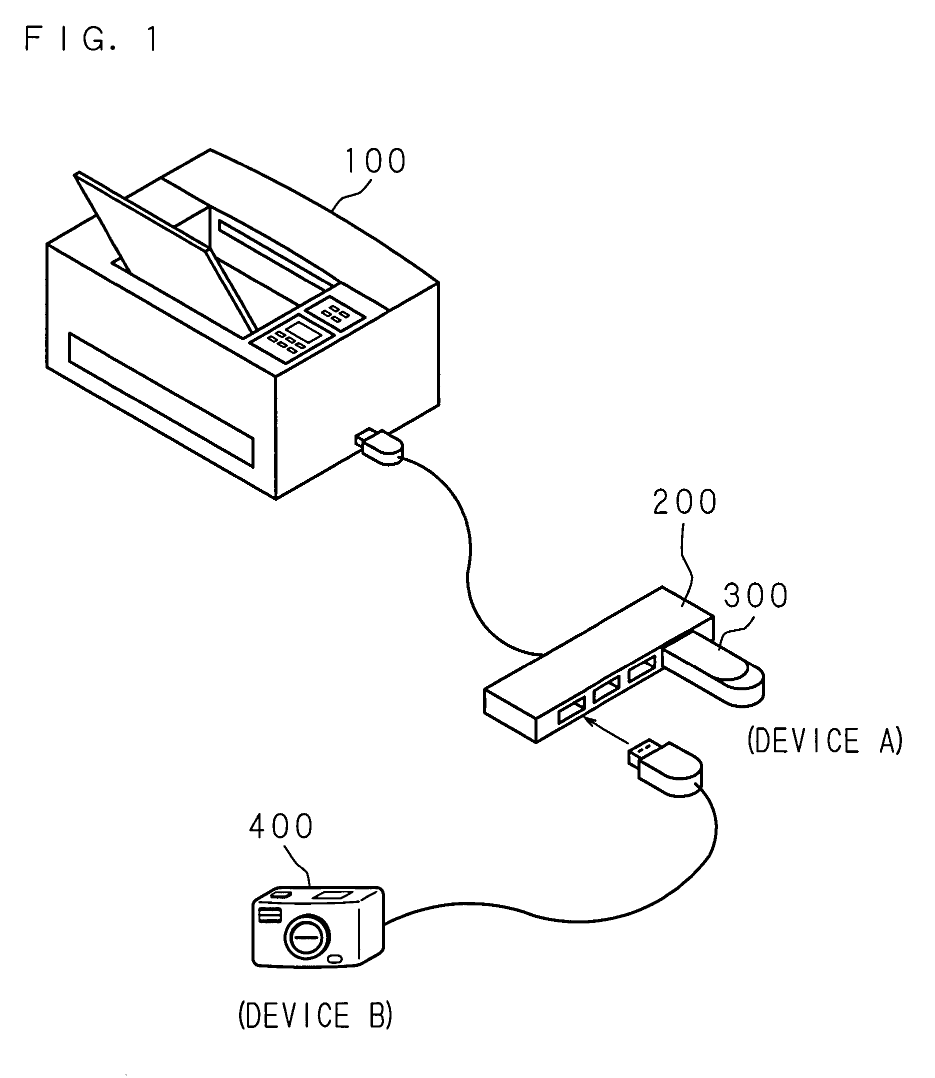
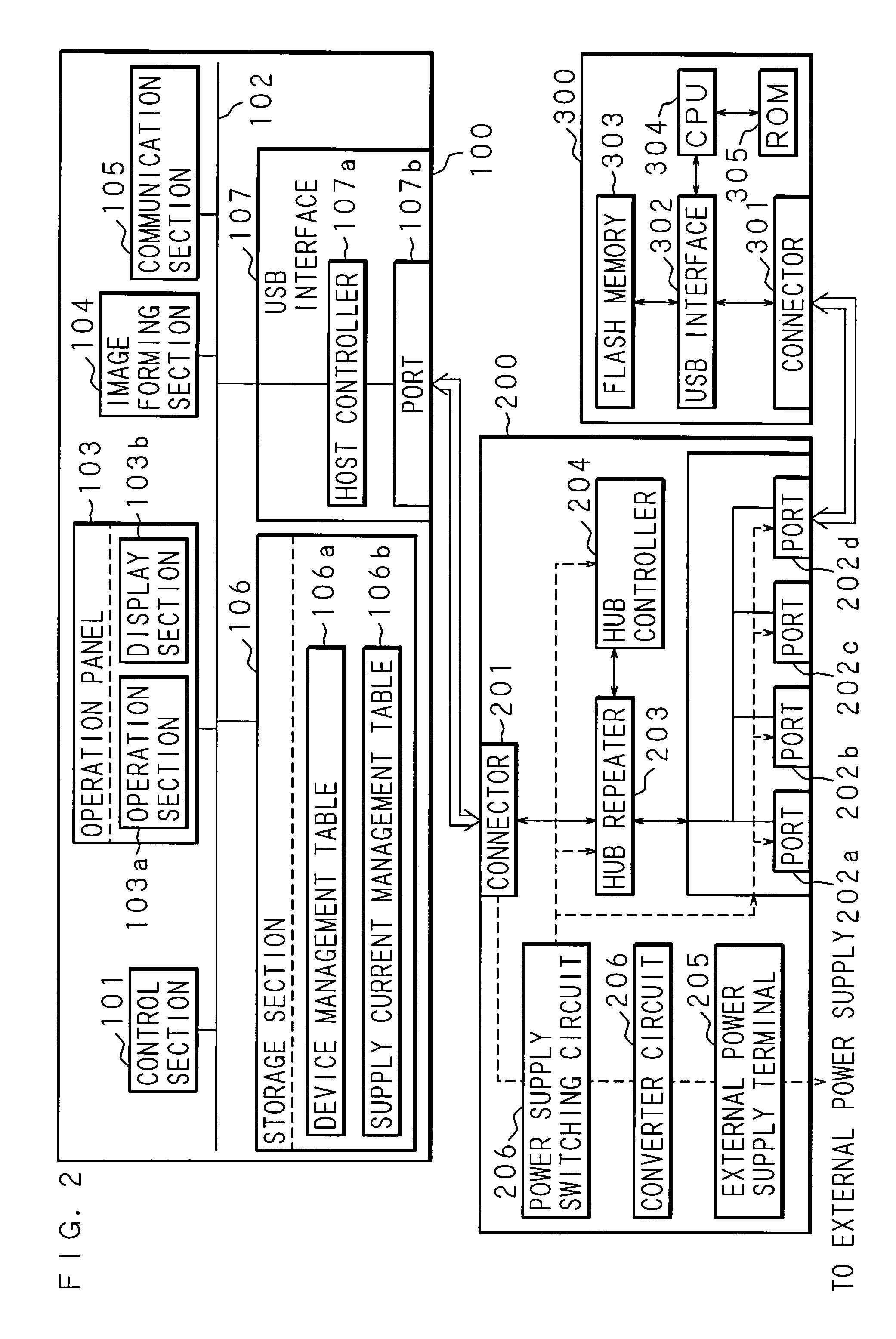
[0062]FIG. 1 is a schematic view illustrating the configuration of a control system according to this embodiment. Numeral 100 in the figure designates an image forming apparatus serving as a USB host. The image forming apparatus 100 is equipped with one USB port (port 107b; see FIG. 2), and controls the operation of a USB device connected to this port 107b or the operation of a USB device connected to this port 107b via a USB hub. A USB device to be controlled by the image forming apparatus 100 is a USB memory, an HDD apparatus, an MO drive, a digital camera, etc. A USB hub 200 equipped with four USB ports (ports 202a to 202d; see FIG. 2) is connected to the image forming apparatus 100 shown in FIG. 1, and a USB memory 300 has already been connected to the port 202d, one of the ports of this USB hub 200. In addition, a digital camera 400 serving as a new USB device is going to be connected to an empty port.

[0063]Generally, the USB specifications stipulate that the upper limit value ...

embodiment 2

[0090]Embodiment 1 is configured so that, in the case that the device side judges that the device is inoperable in the operation mode designated by the image forming apparatus 100 owing to insufficient power supply, the user is urged to supply power to the USB hub. However, in the case that another device is connected to the USB hub, it may be possible to have a configuration in which the operation mode of the other device is changed to reduce supply current and to securely obtain power to be supplied to the newly connected device. The configuration of the hardware is the same as that of Embodiment 1.

[0091]FIG. 9 and FIG. 10 are flowcharts illustrating an operation procedure in the case that a USB device is newly connected. The processing steps from the detection of a newly connected device to the reception of a notice regarding whether the device is operable are carried out in the same way as in Embodiment 1 (step S41 to step S51). In the case that the image forming apparatus 100 h...

embodiment 3

[0099]Embodiment 1 is configured so that, in the case that the device side judges that the device is inoperable in the operation mode designated by the image forming apparatus 100 owing to insufficient power supply, the user is urged to supply power to the USB hub. However, in the case that another device is connected to the USB hub, it may be possible to have a configuration in which the power supply to the other device is shut off to securely obtain power to be supplied to the newly connected device. The configuration of the hardware is the same as that of Embodiment 1.

[0100]FIG. 11 and FIG. 12 are flowcharts illustrating an operation procedure in the case that a USB device is newly connected. The processing steps from the detection of a newly connected device to the reception of a notice regarding whether the device is operable are carried out in the same way as in Embodiment 1 (step S61 to step S71). In the case that the image forming apparatus 100 has received the notice return...


PUM


Abstract

A control system comprising an electronic device equipped with a port, a hub being connectable to multiple external devices and to be connected to the port of the electronic device, and one or more external devices to be connected to the hub, the operation of the external devices connected via the hub being controlled using the electronic device, wherein the electronic device comprises a supplying section for supplying currents to the hub connected to the port and the external devices connected via the hub, and a storage section for storing the magnitude of the total current supplied from the supplying section.

Description

CROSS-REFERENCE TO RELATED APPLICATIONS[0001]This Nonprovisional application claims priority under 35 U.S.C. §119(a) on Patent Application No. 2005-261226 filed in Japan on Sep. 8, 2005, the entire contents for which are hereby incorporated by reference.BACKGROUND OF THE INVENTION[0002]1. Field of the Invention[0003]The present invention relates to a control system, an electronic apparatus and an image forming apparatus, for managing the magnitude of the total current supplied to external devices connected via a hub in order to control operation at the time of the connection.[0004]2. Description of Related Art[0005]In recent years, some image forming apparatuses, such as copiers, printers and digital combination apparatuses, are equipped with a USB port, and a system that captures image data stored in an external device, such as a USB memory or a digital still camera, and outputs images has been proposed (see, for example, Japanese Patent Application Laid-Open No. 2004-109765).[0006...

Claims


Application Information

Patent Timeline
Patent Type & Authority Patents(United States)
IPC IPC(8): G06F13/36G06F1/00G06F11/30G06F13/00H05K7/10
CPCG06F1/26
Inventor HAYASHI, MOTOHIROOGASAWARA, KENJIARAI, MARIKO
Owner SHARP KK
Why Eureka
Try Eureka