Dispenser having elastomer discharge valve

a pump dispenser and elastomer technology, applied in the direction of liquid transfer devices, instruments, volume meters, etc., can solve the problems of increasing the likelihood of the dispenser failing, complex design thereof, and increasing the failure probability of one or more components, so as to improve the deformable outlet valve, improve the effect of the deformation and the ability to discharg

Active Publication Date: 2010-02-02
SILGAN DISPENSING SYST CORP
View PDF42 Cites 12 Cited by
  • Summary
  • Abstract
  • Description
  • Claims
  • Application Information

AI Technical Summary

Benefits of technology

[0011]The invention solves the problems and overcomes the drawbacks and deficiencies of prior art pump dispenser designs by providing in combination an improved deformable outlet valve which both facilitates manufacture and assembly of the pump dispenser, and which provides repeatability in the cross-sectional quality of the discharged product over the life of the pump dispenser.
[0012]The present invention thus provides a manual pump dispenser including a plunger head reciprocable between pressure and return strokes. The pump dispenser may include a pump body having an inlet valve for inletting of a liquid product into the pump dispenser during each of the return strokes, and a discharge valve assembly fitted to a spout provided with the pump body. The discharge valve assembly may permit selective outletting of the liquid product through the spout during each of the pressure strokes. The spout may include a bore having a predetermined diameter. The discharge valve assembly may include a unitary valve disposed substantially within the bore, the unitary valve having an outer diameter smaller than the predetermined diameter. The unitary valve may be made of a material for permitting predetermined axial and radial expansion of the unitary valve under pressure from the liquid product during each of the pressure strokes for thereby allowing the liquid product to be discharged out through a slitted opening at an outlet end of the unitary valve, and enabling rapid contraction of the unitary valve against a valve seat to prevent the liquid product from being discharged through the slitted opening.

Problems solved by technology

However, the provision of the extra fixed ring 137 or 237 requires an extra part for securing cap 135 during manufacture of the pump dispenser, and further increases the likelihood of the dispenser failing due to dislodgement of cap 135 during repeated pumping operation.
Further, the valve assembly disclosed in FIG. 1 of the '258 Patent includes at least three components fitted together for adequate operation, namely first and second valve bodies 7, 11, respectively, and stopper 22, which render the design thereof complex with regard to the manufacture thereof, and which further increase the odds of failure of one or more of the components.

Method used


Image

  • Dispenser having elastomer discharge valve
  • Dispenser having elastomer discharge valve
  • Dispenser having elastomer discharge valve

Examples


first embodiment

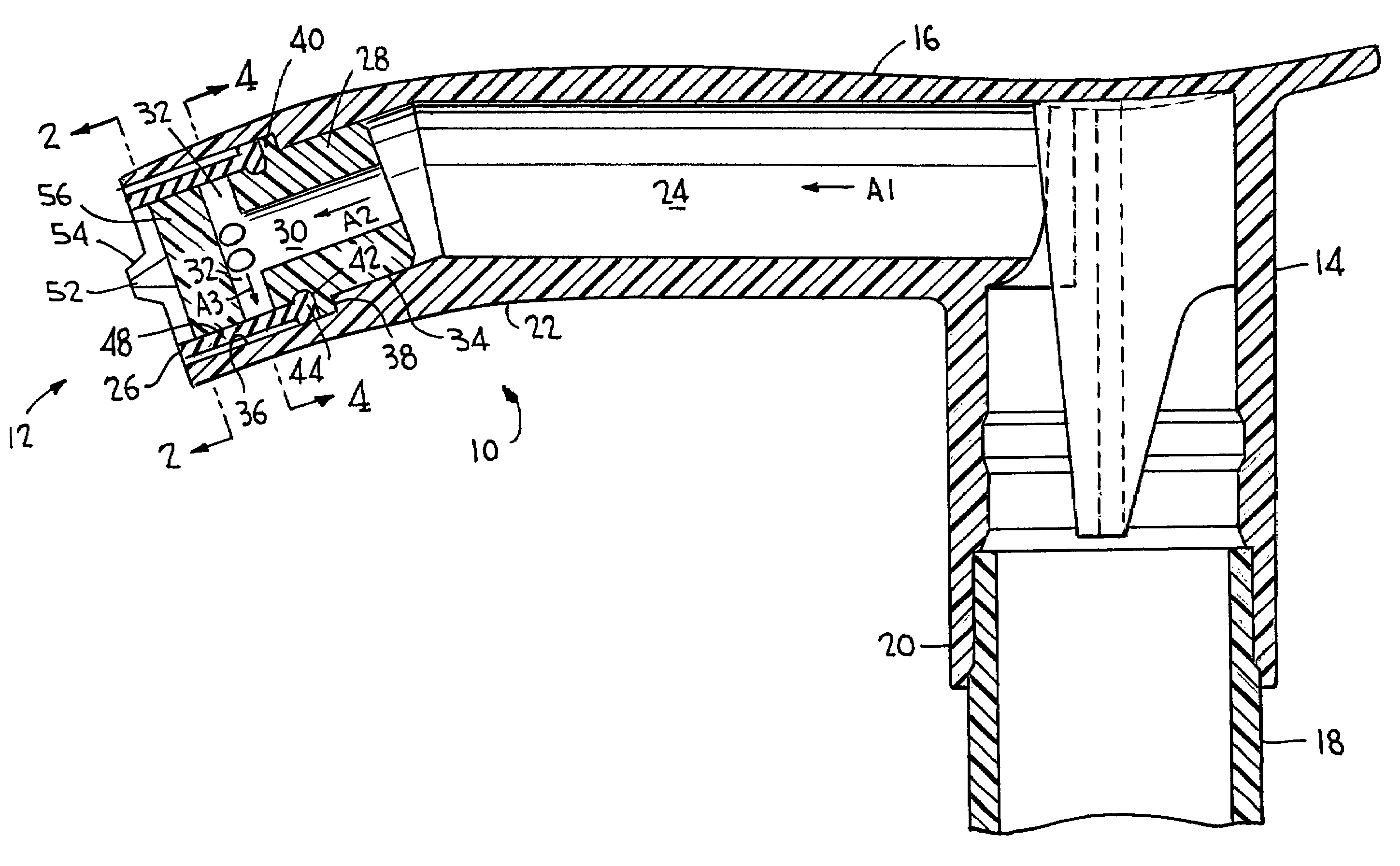
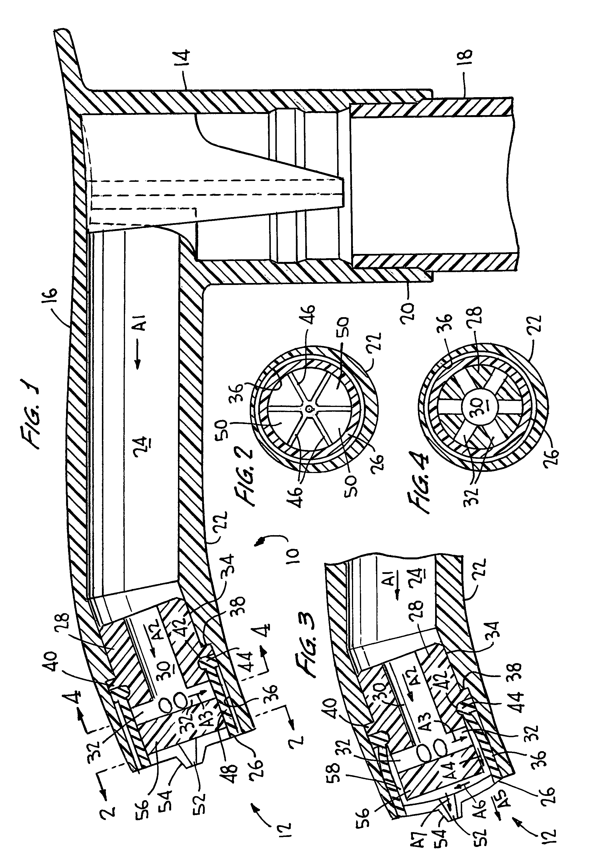
[0038]Referring now to the drawings wherein like reference numerals designate like and corresponding parts throughout the several views, FIGS. 1-4 illustrate a pump dispenser according to the present invention, generally designated 10.

[0039]As shown in FIG. 1, a manually operated pump dispenser 10 of a type which incorporates discharge valve assembly 12 according to the invention comprises a pump body which includes a pump cylinder (not shown) adapted to be affixed to a container (not shown) of product to be dispensed in a conventional manner, as described in detail in U.S. patent application Ser. No. 10 / 214,160, titled “Pump Dispenser Having an Improved Discharge Valve,” owned by the Assignee of the present invention, and the disclosure of which is incorporated herein by reference. As also described in detail in U.S. patent application Ser. No. 10 / 214,160, the pump cylinder may be adapted to be affixed to a container by means of a closure cap which may be internally threaded or whi...

second embodiment

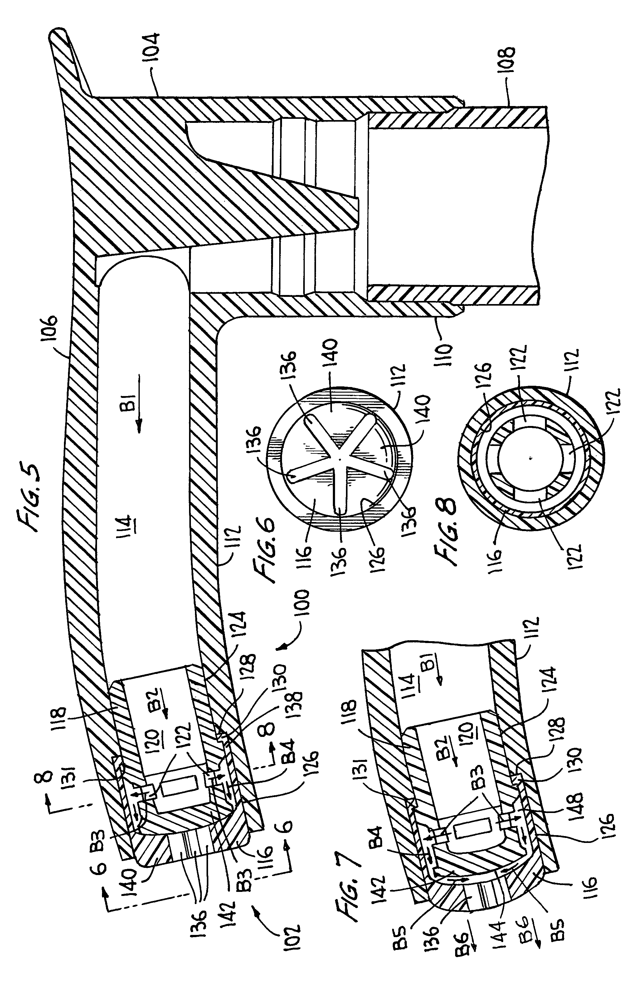
[0047]pump dispenser 100 will now be described in detail with reference to FIGS. 5-8.

[0048]As shown in FIG. 5, in a similar manner as the first embodiment of pump dispenser 10, pump dispenser 100 may likewise be a manually operated pump dispenser, described in detail in the aforementioned U.S. patent application Ser. No. 10 / 214,160. In addition to the standard components described above for pump dispenser 10, pump dispenser 100 may include a discharge valve assembly 102 and a depending sleeve 104 for mounting plunger head 106 to an upper end of hollow piston stem 108 of a piston having at its lower end an annular piston seal (not shown) in sliding sealing engagement with the inner wall of a pump cylinder. Plunger head 106 may include a depending sleeve 110 which frictionally engages the upper end of piston stem 108 to effect a tight seal, and an elongated transverse spout 112 defining a discharge passage 114 which directly communicates with the upper end of the piston stem.

[0049]Ref...

third embodiment

[0055]pump dispenser 200 will now be described in detail with reference to FIGS. 9-12.

[0056]As shown in FIG. 9, in a similar manner as the first and second embodiments of pump dispensers 10 and 100, respectively, pump dispenser 200 may likewise be a manually operated pump dispenser, described in detail in the aforementioned U.S. patent application Ser. No. 10 / 214,160. In addition to the standard components described above for pump dispensers 10 and 100, pump dispenser 200 may include a discharge valve assembly 202 and a depending sleeve 204 for mounting plunger head 206 to an upper end of hollow piston stem 208 of a piston having at its lower end an annular piston seal (not shown) in sliding sealing engagement with the inner wall of a pump cylinder. Plunger head 206 may include a depending sleeve 210 which frictionally engages the upper end of piston stem 208 to effect a tight seal, and an elongated transverse spout 212 defining a discharge passage 214 which directly communicates wi...


PUM


Abstract

A manual pump dispenser includes a plunger head reciprocable between pressure and return strokes, and a pump body having an inlet valve for inletting of liquid product during each of the return strokes. A discharge valve assembly is fitted to a spout for permitting selective outletting of liquid product through the spout during each of the pressure strokes. The spout includes a bore having a predetermined diameter, with a unitary valve disposed substantially within the bore. The unitary valve is made of a material for permitting predetermined axial, or axial and radial expansion thereof under pressure from liquid product during each of the pressure strokes for thereby allowing liquid product to be discharged through a slitted opening in the unitary valve, and enabling rapid contraction thereof against a valve seat to prevent liquid product from being discharged through the slitted opening.

Description

BACKGROUND OF INVENTION[0001]a. Field of Invention[0002]The invention relates generally to a manually actuated pump dispenser having an improved discharge valve member, and more particularly to such a valve member of elastomeric material capable of a quick shut-off of the discharge and having a slitted valve element for discharging personal use products such as hand lotions or the like.[0003]b. Description of Related Art[0004]The known manually actuated pump dispensers especially those designed for the dispensing of hand lotions, body lotions, liquid soaps, and other viscous products, typically have both inlet and outlet ball check valves for respectively controlling the flow of liquid product into the pump chamber on each piston suction stroke and for controlling the outflow of the liquid product from the pump chamber during each piston compression stroke. Alternatively, such dispensers may include an inlet ball check valve for controlling the flow of liquid product into the pump c...

Claims


Application Information

Patent Timeline
Patent Type & Authority Patents(United States)
IPC IPC(8): G01F11/00B67D99/00B05B1/32B05B11/00
CPCB05B11/007B05B1/323B65D47/00
Inventor DOBBS, DOUGLAS B.O'NEILL, KEVINPHAN, STEVEN G.
Owner SILGAN DISPENSING SYST CORP
Why Eureka
Try Eureka