Oven

a technology for ovens and doors, applied in the field of ovens, can solve the problems of ineffective cooling of the door by simply forming air passages, and insufficient cooling of the frame, so as to achieve the effect of reducing the amount of heat transferred through the cavity, reducing the amount of heat transferred from the cavity to the side frame, and facilitating dissipation

Active Publication Date: 2010-02-02
LG ELECTRONICS INC
View PDF10 Cites 7 Cited by
  • Summary
  • Abstract
  • Description
  • Claims
  • Application Information

AI Technical Summary

Benefits of technology

[0010]An object of the present invention is to provide an oven door having a structure capable of easily discharging heat transferred from the cavity to the door frame.
[0011]Another object of the present invention is to provide a oven door having a structure capable of reducing the amount of heat transferred from inside the cavity to the door frame.
[0016]In the above-structured oven door according to the present invention, an air receiving hole is formed as a sealed space within the door frame. Thus, the area of the first door panel that directly contacts the cavity and receives heat contacting the side frame is reduced, so that the amount of heat transferred through the cavity is effectively reduced.
[0017]Also, the receiving hole within which inner air is filled blocks the transfer of heat radiated from the cavity, to act as a thermal blocking layer. Accordingly, the amount of heat transferred from the cavity to the side frame is effectively reduced.
[0018]Also, in the structure of the oven door according to the present invention, outside air enters the respective spaces formed between the second door panel, the third door panel, and the fourth door panel, so that heat transferred from the cavity to the door frame can easily be dissipated.
[0019]Furthermore, in the oven door structure according to the present invention, outside air enters and contacts an outer valley protrusion, an inner valley protrusion, a concave protrusion, and the second outer protrusion, and other similar fin portions. The fin portions, being portions protruding from the side frame, enlarges the surface that the moving air contacts. Accordingly, the air moving within the side frame exchanges heat with the fin portions. That is, the amount of heat radiated from the side frame is increased, thereby increasing cooling effectiveness.

Problems solved by technology

However, in the conventional method of simply forming air passages in the door is ineffective in cooling the door.
Especially in door frames made of metal material, the prodigious amount of heat conducted from inside the cavity to the frame is absorbed by the frame, where the structure for radiating the heat absorbed by the frame cannot provide adequate cooling.
Accordingly, heat in the door frame cannot be sufficiently radiated to the outside, so that cooling effectiveness of the door is reduced.

Method used


Image

  • Oven
  • Oven
  • Oven

Examples


Embodiment Construction

[0030]Reference will now be made in detail to the preferred embodiments of the present invention, examples of which are illustrated in the accompanying drawings. Wherever possible, the same reference numbers will be used throughout the drawings to refer to the same or like parts.

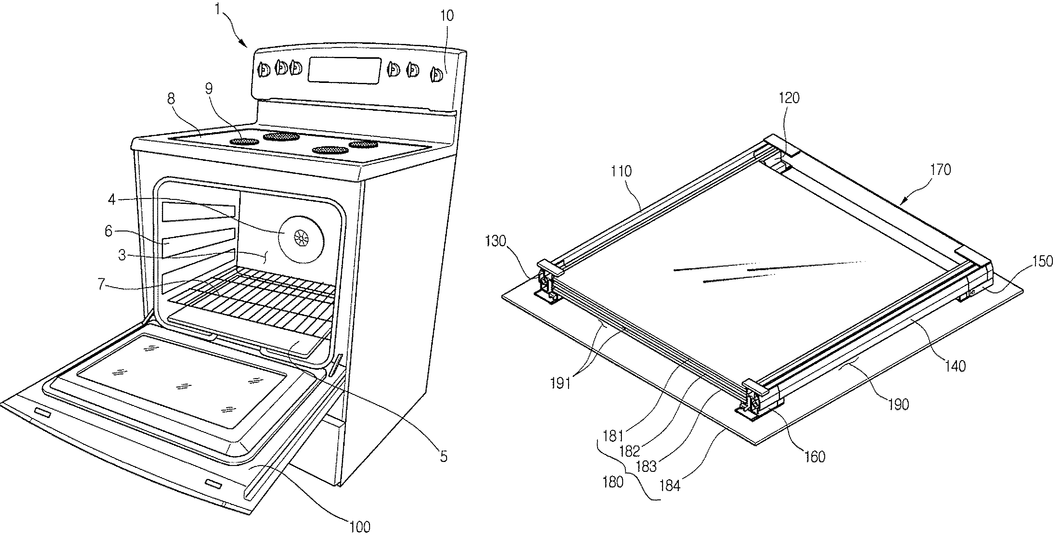
[0031]FIG. 1 is a perspective view of an oven according to the present invention.

[0032]Referring to FIG. 1, an oven 1 according to the present invention includes a cavity 3 forming an inner cooking space within, a door 100 pivotably installed at the front opening of the cavity 3, a convection heater (not shown) provided at the rear interior of the cavity 3 for generating heat, and a convection fan 4 for diffusing the heat generated by the convection fan throughout the inside of the cavity 3.

[0033]In further detail, a sealing member 11 surrounds the edges at the front of the cavity 3. The sealing member 11 seals the space between the door 100 and the cavity 3. The sealing member 11 is installed on the front c...


PUM


Abstract

An oven is provided. The oven includes a cavity, a door panel that covers the cavity, and a side frame that supports a side of the door panel. The side frame and the door frame form an outside air intake hole therebetween.

Description

BACKGROUND OF THE INVENTION[0001]1. Field of the Invention[0002]The present invention relates to an oven, and more particularly, to an oven door structure for an oven with a door frame having improved cooling performance.[0003]2. Description of the Related Art[0004]Generally, an oven is a cooking apparatus that cooks food placed within a cavity by applying heat generated by a heater[0005]Specifically, the cavity can be selectively opened and closed by means of a door pivotably installed at the front of the oven. Also, the door has a skeletal frame on which a door panel and other components are attached.[0006]In ovens according to the related art, in order to cool the door, a separate cooling passage is formed separately within the door. This cooling passage cools the door using air flowing through the passage from the outside of the oven. An exemplary embodiment of such an oven is a structure that suctions outside air at the bottom of the door and circulates the air through the door...

Claims


Application Information

Patent Timeline
Patent Type & Authority Patents(United States)
IPC IPC(8): F24C15/04A21B3/02F24C15/32
CPCF24C15/006F24C15/04F24C15/025
Inventor KIM, JONG SIKKIM, YANG KYEONG
Owner LG ELECTRONICS INC
Why Eureka
Try Eureka