Control module

a control module and control panel technology, applied in the direction of transportation and packaging, electrical apparatus casings/cabinets/drawers, printed circuit non-printed electric components association, etc., can solve the problem of flux not being able to contaminate the ltcc substrate, and achieve low assembly effort, cost-effective manufacturing, and simple structure.

Inactive Publication Date: 2010-02-02
ROBERT BOSCH GMBH
View PDF13 Cites 34 Cited by
  • Summary
  • Abstract
  • Description
  • Claims
  • Application Information

AI Technical Summary

Benefits of technology

[0005]The inventive control module requires particularly little assembly effort and can be manufactured cost-effectively. With a stack-shaped design, with which the carrier—which bears, via a first side, against an interior side of the first housing part on which the circuit part is mounted, and with which the circuit part is located in a recess in the carrier, the flexible conductor film is located on the second side of the carrier which faces away from the first housing part, and the second housing part is placed on the flexible conductor film, there is no need to laminate the flexible conductor film on the first housing part, on which the circuit part is mounted, and it is attained—in a particularly advantageous manner—that the control module can be composed essentially of an assembly for the connection functions, an assembly for the electronics functions, and a cover part. Particularly advantageously, the two assemblies can be manufactured and pretested separately, and then simply stacked in position. The electrical interface between the two assemblies can be designed such that the two assemblies can be connected electrically in a simple, robust manner.
[0006]Since the assembly for the electronics functions can be manufactured without the flexible conductor film, it can be manufactured more cost-effectively, since the assembly of the electronic circuit part and the contacting of the electronic components wit

Problems solved by technology

Since the components are installed during manufacture of the assembly for the connection functions, attention is need not

Method used


Image

  • Control module
  • Control module
  • Control module

Examples


Embodiment Construction

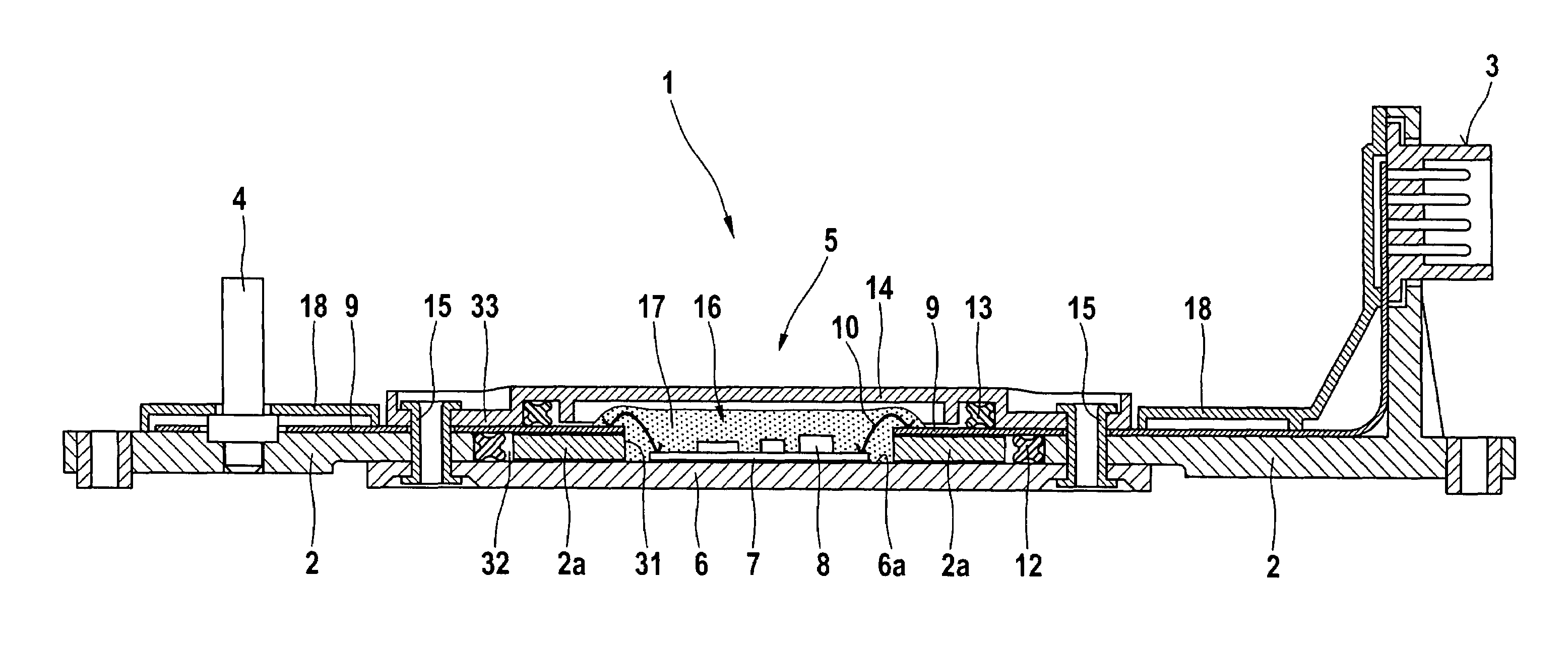
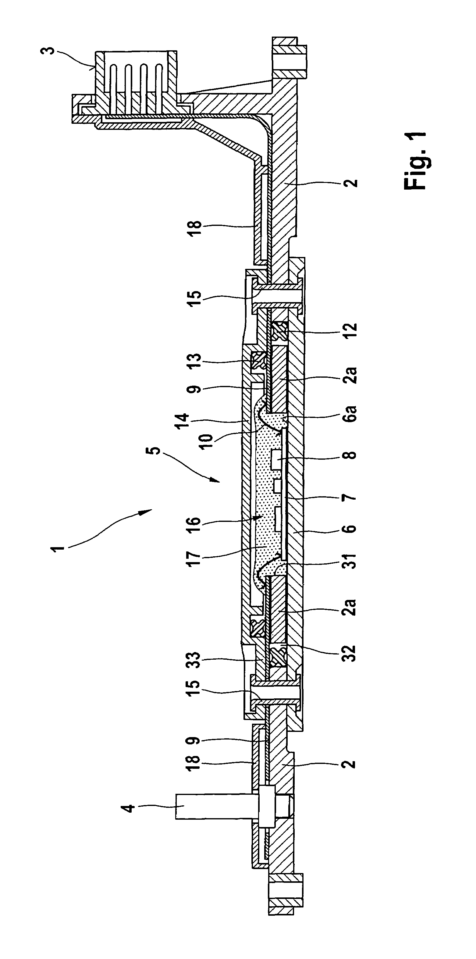
[0017]FIG. 1 shows a cross section through a first exemplary embodiment of the inventive control module. Control module 1 includes a carrier 2 made of metal or plastic, which is mountable, e.g., on the transmission of a motor vehicle, and on which various components are installed, such as sensors 4, a plug connector part 3, and, optionally, hydraulic valves (not shown) for controlling actuators of the transmission, and a transmission control unit 5. Control unit 5 includes a first housing part 6 which is preferably designed as a metallic base plate, e.g., out of aluminum. An electronic circuit part 7, e.g., a LTCC (low-temperature cofired ceramic) substrate, on which electronic components 8 are installed, is bonded to the interior side 6a of first housing part 6. Components 8 can be connected via gold bonding wires with the conductive tracks of the LTCC substrate. Circuit part 7 is connected with a flexible conductor film 9 via contact elements, e.g., aluminum bonding wires 10. Flex...


PUM

PropertyMeasurementUnit
Flexibilityaaaaaaaaaa

Abstract

A control module, in particular for a motor vehicle transmission, which includes a first housing part, on which an electronic circuit part is located, a second housing part, and a carrier, on which a flexible conductor film is located; the flexible conductor film is electrically connected—in a housing interior located between the first housing part and the second housing part—with the circuit part and the flexible conductor film is electrically connected outside of the housing interior—with electrical components mounted on the carrier, the control module having a stack-shaped design, with which the carrier rests, via a first side, on an interior side of the first housing part on which the circuit part is mounted, the circuit part is located in a recess in the carrier, the flexible conductor film is located on the second side of carrier, which faces away from the first housing part, and the second housing part is mounted on a side of the flexible conductor film facing away from the second side of the carrier.

Description

CROSS-REFERENCE TO RELATED APPLICATION[0001]The invention described and claimed hereinbelow is also described in German Patent Application DE 10 2005 002 813.6-14 filed on Jan. 20, 2005. This German Patent Application provides the basis for a claim of priority of invention under 35 U.S.C. 119(a)-(d).BACKGROUND OF THE INVENTION[0002]The present invention relates to a control module, in particular a control module for a motor vehicle transmission.[0003]A control module with the features listed in the preamble of claim 1 is made known, e.g., in DE 199 07 949 A1. Control modules of this type are designed to be mounted on a motor vehicle component such as the transmission or the engine, and have various components which are assigned to the motor vehicle components. Control modules for automatic transmissions include, e.g., a hybrid control unit with an electronic circuit part, sensors, and at least one plug connector for connecting to the vehicle wiring harness; some of them are located ...

Claims


Application Information

Patent Timeline
IPC IPC(8): H05K5/00
CPCF16H61/0006H05K1/147H05K5/0082H05K3/0061Y10T29/49117H01L2224/48091H01L2224/48227H01L2224/48472H05K2203/049H01L2924/00014H01L2924/00B60R16/00H05K1/18H05K5/00
Inventor WETZEL, GERHARDSPRAFKE, PETER
Owner ROBERT BOSCH GMBH
Why Eureka
Try Eureka