Efficient timing graph update for dynamic netlist changes

a dynamic netlist and graph update technology, applied in the field of physical design of electronic circuits, can solve problems such as invalidating previous graph representations, difficult to determine interconnection delays, and changes that may be required in the topology of input netlist and circuits

Active Publication Date: 2010-02-02
XILINX INC
View PDF14 Cites 57 Cited by
  • Summary
  • Abstract
  • Description
  • Claims
  • Application Information

AI Technical Summary

Benefits of technology

[0007]The various embodiments of the invention provide a number of approaches for implementing an electronic design. In one embodiment, the design's timing is represented by a timing graph that includes nodes and their connections, or arcs. Portions of the timing graph are identified for potent

Problems solved by technology

However, interconnection delays may be difficult to determine because the routing between logic has not yet been determined.
A problem with synthesis optimizations is that changes may be required in the topology of the input netlist and the circuit.
Such changes may invalidate any previous graph representations and require regeneration of the timin

Method used


Image

  • Efficient timing graph update for dynamic netlist changes
  • Efficient timing graph update for dynamic netlist changes
  • Efficient timing graph update for dynamic netlist changes

Examples


Embodiment Construction

[0020]The various embodiments of the invention provide methods and apparatus for optimizing an integrated circuit design. One or more aspects in accordance with the invention are described in terms of a field programmable gate array (FPGA). While specific reference is made to an FPGA, those skilled in the art will appreciate that one or more aspects of the invention may be used for designing other types of integrated circuits, such as complex programmable logic devices (CPLDs), application specific integrated circuits (ASICs), and the like.

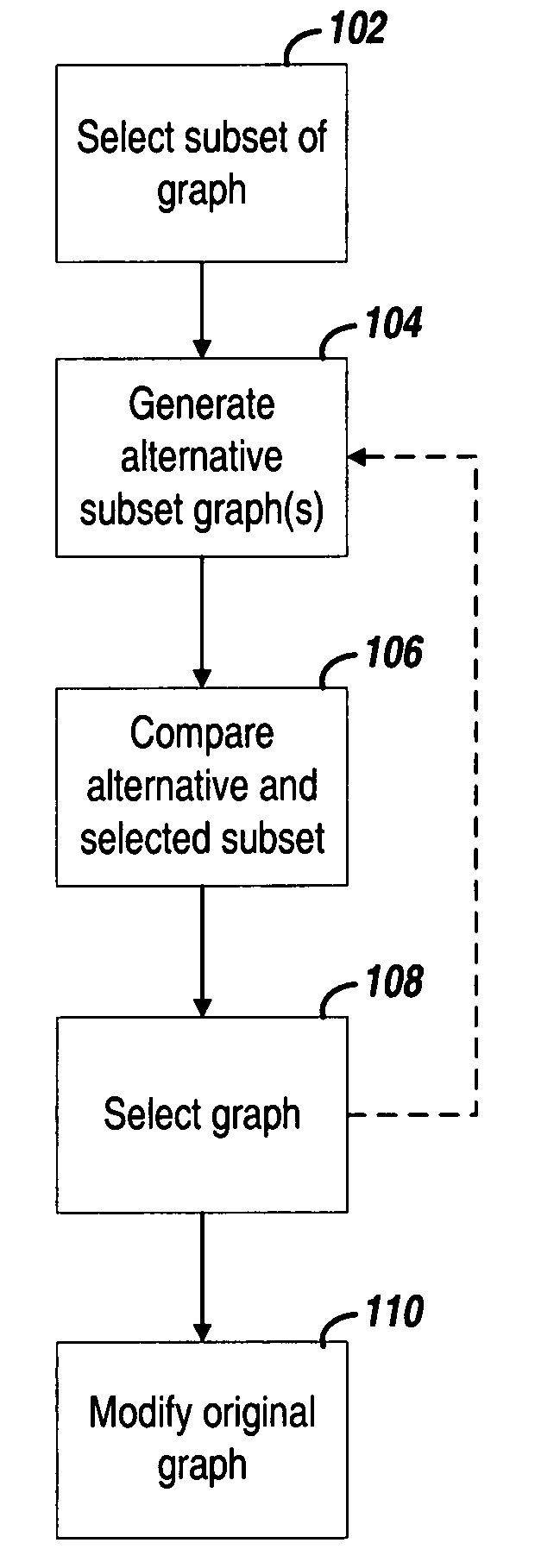
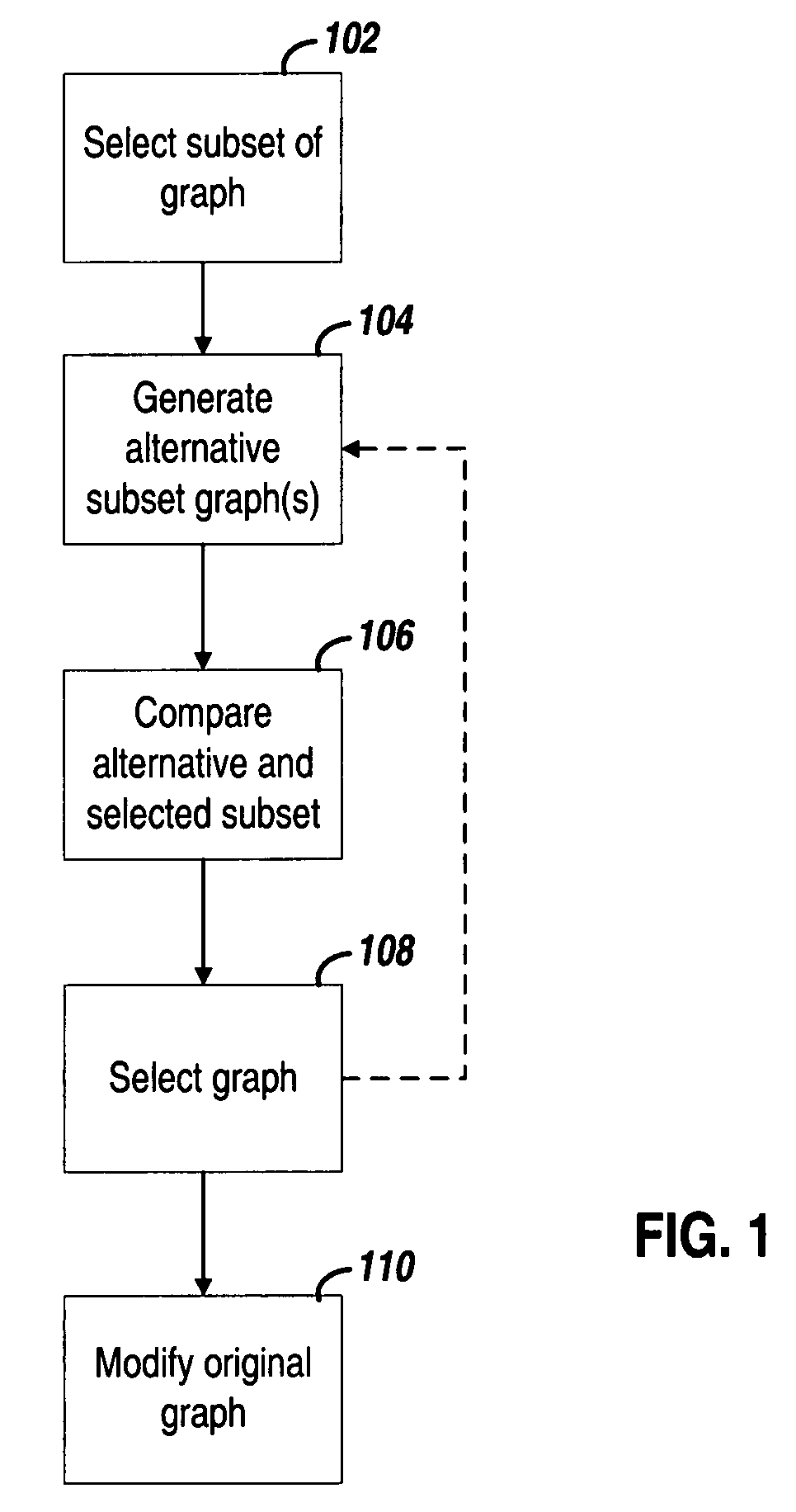
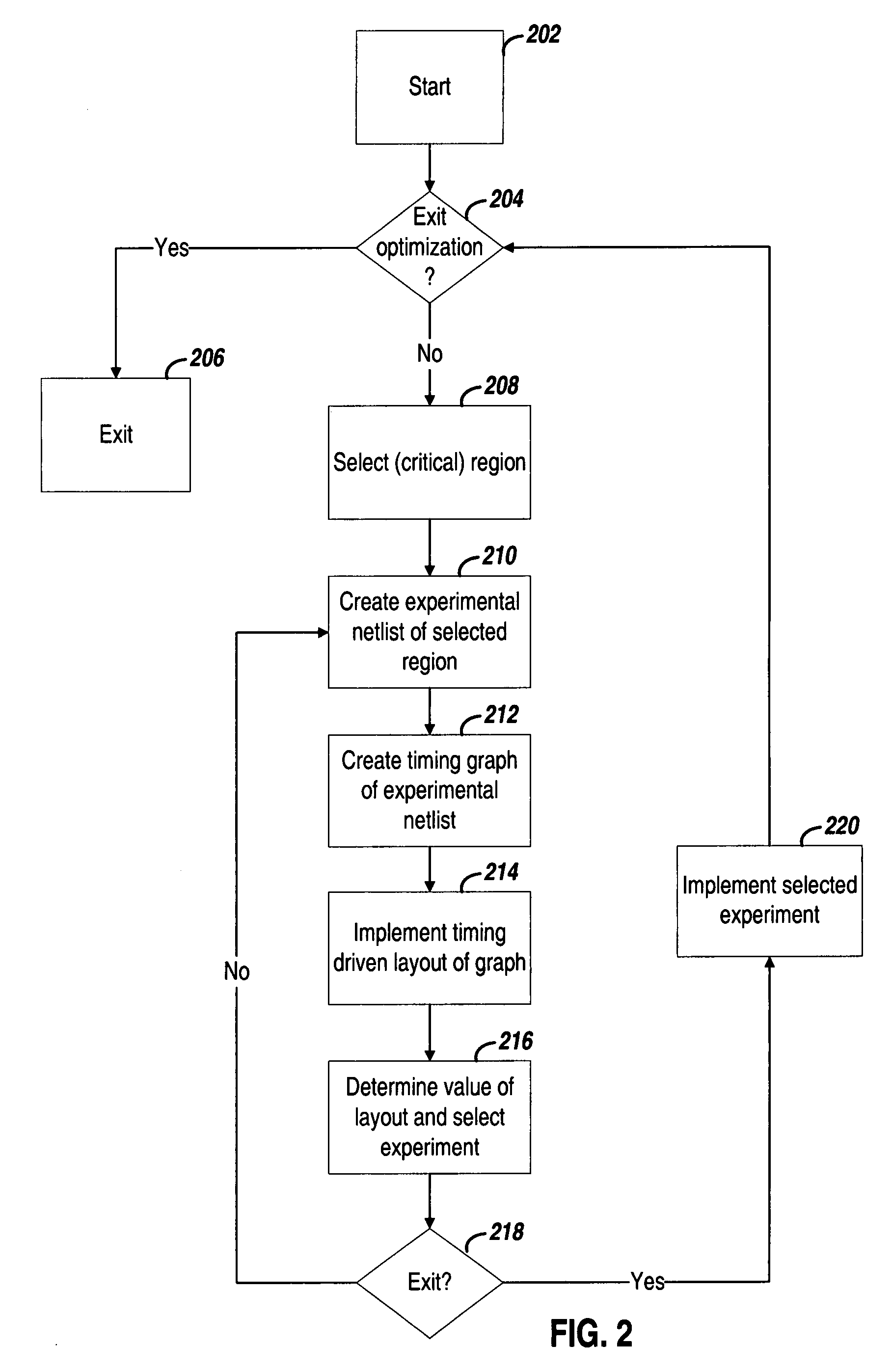
[0021]Consistent with one example embodiment of the present invention, a computer implemented method identifies potential design optimizations and provides dynamically updated timing states that correspond to selected optimizations. The identification and implementation of the optimization may be performed after the place-and-route stage of the design flow. This may be particularly useful for implementing optimizations that benefit from the use of...


PUM


Abstract

Various approaches for incrementally updating the timing of an implementation of an electronic circuit design are disclosed. In one approach, a subset timing graph is selected from a primary timing graph. Alternative subset timing graphs are generated that are functionally equivalent and structurally different with respect to the selected subset timing graph. For each of the alternative timing graphs, a respective timing metric is determined. The determined timing metrics and a timing metric for the selected subset timing graph are compared. An alternative timing graph is selected in response to the comparison. Structurally different portions of the selected one of the one or more alternative timing graphs are verified with regard to the design constraints. The structurally different portions are stored to the primary timing graph.

Description

FIELD OF THE INVENTION[0001]The present invention generally relates to physical design of electronic circuits, and more particularly to improving the physical design of a programmable logic device through netlist changes.BACKGROUND[0002]Programmable logic devices (PLDs), such as field-programmable gate arrays (FPGAs), are user-programmable integrated circuits that can be programmed to implement user-defined logic circuits. In a typical FPGA architecture, an array of configurable logic blocks (CLBs) and a programmable interconnect structure are surrounded by a ring of programmable input / output blocks (IOBs). Other FPGA architectures implement columns of IOBs, memory blocks and hard cores throughout the logic array. The programmable interconnect structure comprises interconnects and configuration memory cells. Each of the CLBs and the IOBs also includes configuration memory cells. The content of the configuration memory cells determines how the CLBs, the IOBs and the programmable inte...

Claims


Application Information

Patent Timeline
IPC IPC(8): G06F17/50
CPCG06F17/5031G06F30/3312
Inventor MANAKER, JR., WALTER A.MEZEI, NICHOLAS A.EWING, DAVID A.SRINIVASAN, SANKARANARAYANAN
Owner XILINX INC
Why Eureka
Try Eureka