
Method and apparatus for manufacturing interchangeable and replaceable parts

a technology of replaceable parts and manufacturing methods, applied in the manufacture of metal-working machine components, manufacturing tools, transportation and packaging, etc., can solve the problems of preventing proper installation, preventing proper installation, and requiring the use of the entire structure, and achieve the effect of freeing up tolerances

Active Publication Date: 2010-02-09
TEXTRON INNOVATIONS
View PDF6 Cites 12 Cited by
  • Summary
  • Abstract
  • Description
  • Claims
  • Application Information

AI Technical Summary

Benefits of technology

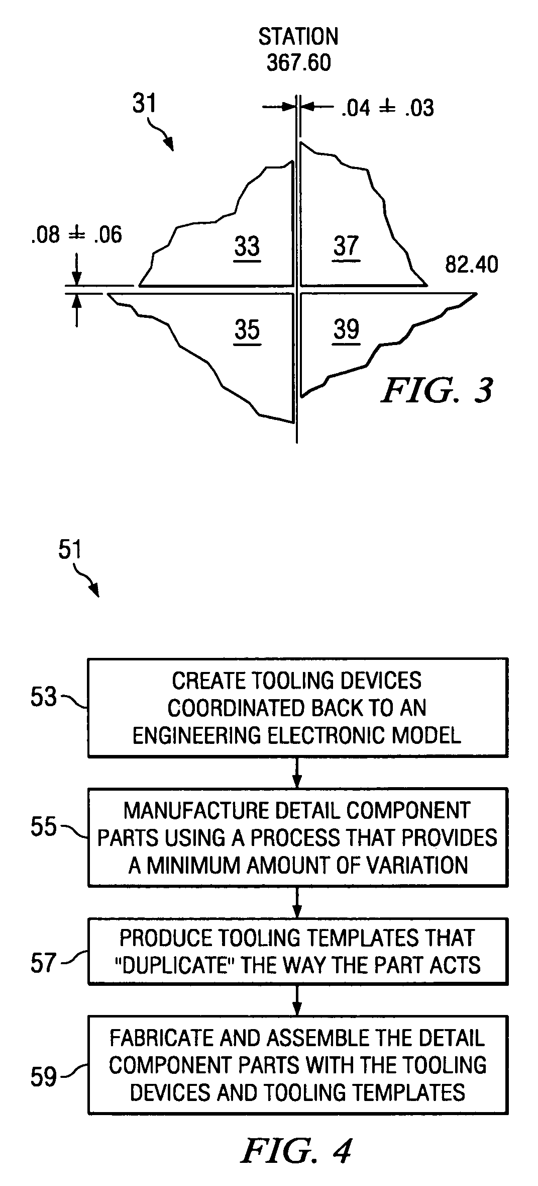
The present invention provides a method and apparatus for manufacturing interchangeable and replaceable component parts. The method and apparatus use a specific production process and tooling methodology that can control tolerance stack-ups and process variation at each step in the process. The control tools are more closely coordinated with engineering nominals, and the detail tool families are not susceptible to deformation. The faying surfaces of the substructure and panels can be controlled during assembly, and critical features are fixture located during assembly. Numerically controlled tooling devices that can machine parts very precisely are used, thereby freeing up tolerances. Additionally, assembly variation reducing and compensating measures are implemented.

Problems solved by technology

There are two main problems associated with manufacturing interchangeable and replaceable parts: (1) if the individual parts are not manufactured to be identical to each other, they will not properly align with the structure and other component parts, thereby preventing proper installation; and (2) if the tolerances of the individual parts are not carefully maintained, the tolerances stack up, and eventually, a part will be misaligned, thereby preventing proper installation.
The latter problem is particularly prevalent in structures where multiple component parts are installed adjacent to each other, such as when the component parts are panels that form a skin over an underlying frame structure.
Often, if a component part becomes damaged or is in need or replacement, the entire structure must be taken out of use until the component part is replaced.
In many instances, the replacement parts do not match the original parts closely enough, and must be either reworked to fit, or not used at all.
Reworking replacement parts is an expensive and time consuming process, often resulting in component parts that do not conform to original design specifications being installed on the structure.
In addition, it is practically impossible to maintain an inventory of every individual component part, if every individual component part has previously undergone unique drilling, reaming, cutting, etc., operations before being initially installed onto an the structure.
Aircraft travel great distances and are often many miles away from a hub or repair facility.
If a component part on an aircraft, such as a panel on a wing or fuselage, becomes damaged or is in need or replacement, the aircraft must be grounded until the component part is replaced.
Often, the replacement part must be shipped from great distances.
This is very time consuming and costly.
This problem of stocking, shipping, and maintaining a supply of replacement parts for aircraft is particularly acute in the military.
Previous methods and apparatuses to achieve interchangeability and replaceability have been unsuccessful.
These carbon epoxy bond molds degrade over time resulting in contours that deviated from nominal.
Additionally, the substructure frames of the nacelle are found to deviate from engineering nominal values due to a coefficient of thermal expansion difference between the material and the bond molds.
As a result of the spring back caused by this coefficient of thermal expansion difference, the outer mold line of the structure cannot be controlled adequately.
Compounding that problem is the variation in detail panel contour.
However, due to the complexity of the design of most panels, and the limitations of single rail hand routers, hand routing is simply not capable of repeatedly providing trim on detail parts that meet engineering specifications.
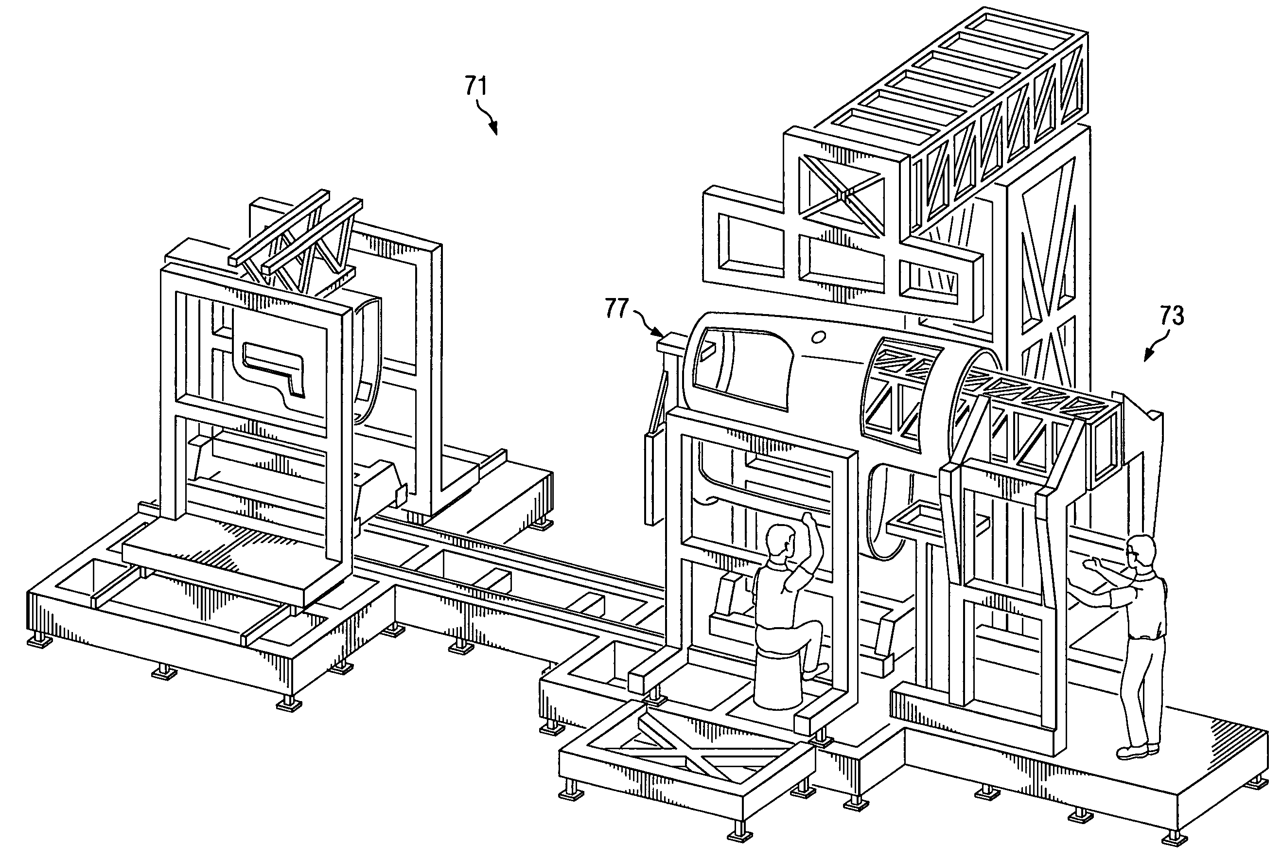
The drawbacks to this method are significant, and include: (1) the control tools deviate from engineering nominals; (2) the detail tool families deviate from the control tools; (3) faying surfaces (structural and panels) cannot be controlled during assembly; and (4) the assembly fixtures do not fixture locate critical features.

Method used


Image

  • Method and apparatus for manufacturing interchangeable and replaceable parts
  • Method and apparatus for manufacturing interchangeable and replaceable parts
  • Method and apparatus for manufacturing interchangeable and replaceable parts

Examples


Embodiment Construction

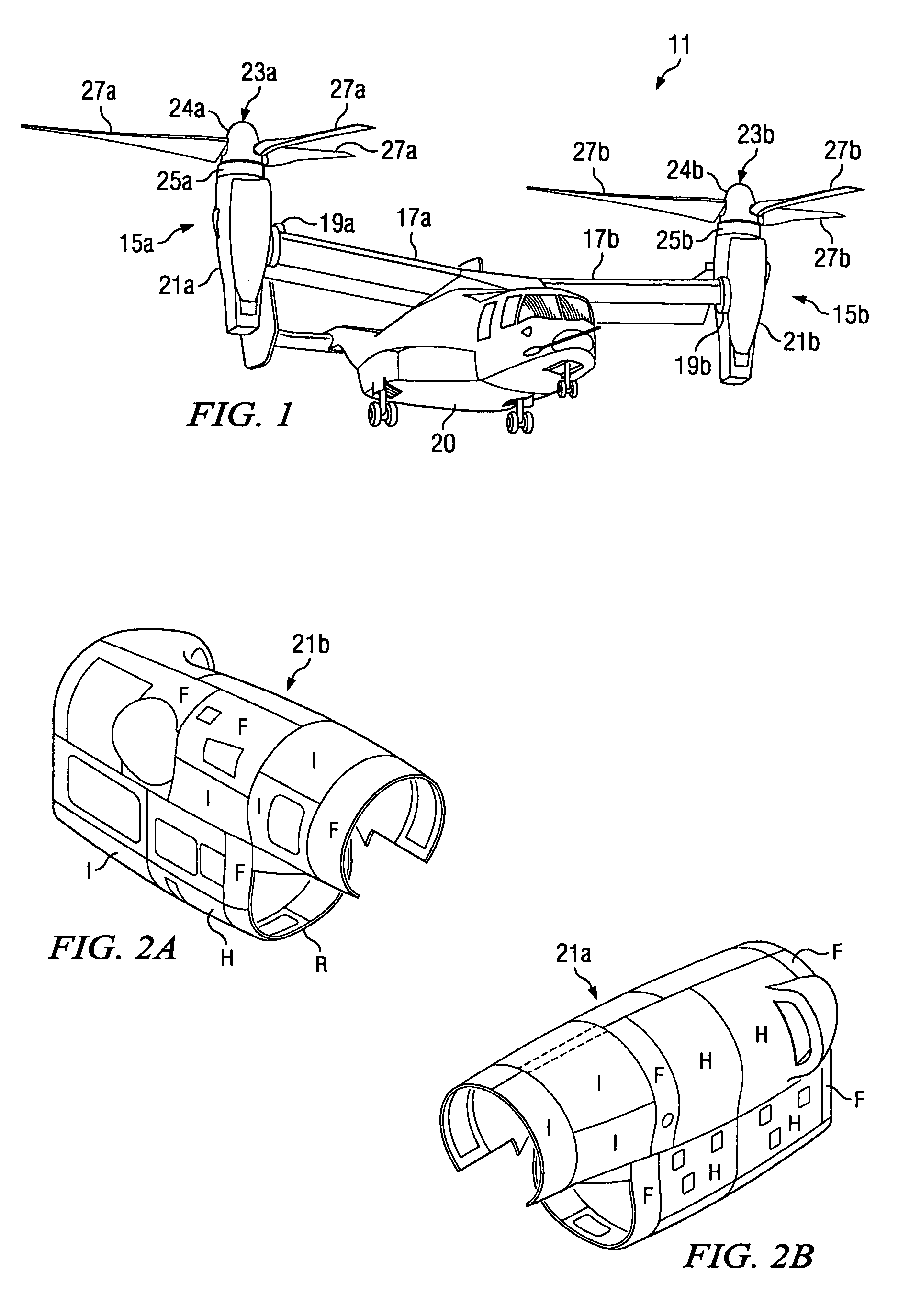
[0025]It will be appreciated that the present invention can be used in wide variety of manufacturing applications. One application that is particularly well suited for the present invention is the manufacturing of panels that are assembled to form the skins of aircraft, such as the wings, fuselage, and nacelles of tiltrotor aircraft. Thus, although the present invention will be described with respect to the manufacture and assembly of interchangeable and replaceable component parts for a nacelle of a tiltrotor aircraft, it should be understood that the present invention may be used in any industry and or manufacturing application in which close relative positional tolerances are required in combination with fully interchangeable and replaceable component parts.

[0026]Referring to FIG. 1 in the drawings, a military-type tiltrotor aircraft 11 having interchangeable and replaceable component parts manufactured according to the method and apparatuses of the present invention is illustrat...


PUM

PropertyMeasurementUnit
diameteraaaaaaaaaa
structuresaaaaaaaaaa
distancesaaaaaaaaaa

Abstract

A manufacturing method and apparatus is disclosed, whereby a specific production process is used in conjunction with a specific tooling methodology to provide a tooling process package that is capable of controlling tolerance stack-ups and process variations by accounting for them at each step in the process. One application particularly suited for the present invention is in the manufacturing of panels that are assembled to form the skins of a tiltrotor aircraft (11).

Description

GOVERNMENT LICENSE RIGHTS[0001]The U.S. Government has a paid-up license in this invention and the right in limited circumstances to require the patent owner to license others on reasonable terms as provided for by the terms of Contract No. N00019-93-C-0006 awarded by NAVAIR.TECHNICAL FIELD[0002]The present invention relates to the manufacturing of component parts for assembly into larger structures. In particular, the present invention relates to the manufacture of interchangeable and replaceable component panels.DESCRIPTION OF THE PRIOR ART[0003]Most complicated structures are assembled from a number of smaller component parts. In designing these complicated structures, it is desirable to have the component parts be replaceable and interchangeable. That way, the component parts can be quickly and easily replaced and interchanged between structures as needed during maintenance of the structures. For purposes of this application, interchangeable parts are defined as component parts ...

Claims


Application Information

Patent Timeline
Patent Type & Authority Patents(United States)
IPC IPC(8): B23Q3/00B64C1/00B21D53/88B23P21/00B64F5/00G01N1/22G01N1/24
CPCB21D53/88B23P21/00B64F5/0009Y10T29/49622Y10T29/49895B64C2211/00B64F5/10
Inventor GREENE, MICHAEL A.
Owner TEXTRON INNOVATIONS
Learn More