High pressure system

a high-pressure system and high-pressure technology, applied in the direction of drilling pipes, drilling/well accessories, sealing/packing, etc., can solve the problems of preventing the rig from being able, running all of this equipment is very time-consuming, and it is not possible to change from running wireline or coiled tubing equipment into the well, so as to achieve more effective and rapid

Inactive Publication Date: 2010-02-09
ENHANCED DRILLING
View PDF6 Cites 105 Cited by
  • Summary
  • Abstract
  • Description
  • Claims
  • Application Information

AI Technical Summary

Problems solved by technology

To run all of this equipment is very time consuming, in that the rig crew first has to run the 21″ marine drilling riser and the 18¾″ drilling BOP and suspend this system in the drilling rig's riser tension system underneath the rig floor.
This will also prevent the rig from being able to run jointed drillpipe into the well, since the equipment for running jointed pipe is occupied holding tension in the riser system.
Hence with prior art, it is not possible to change from running wireline or coiled tubing equipment into the well, into the process of running jointed drillpipe into the well or vice versa, without having to change out the whole riser system or disconnecting the riser from the production sub-sea x-mas tree.
This riser would not be able to tolerate high pressures from the well.
In deeper waters this will take considerable amount of time.

Method used


Image

  • High pressure system
  • High pressure system
  • High pressure system

Examples


Embodiment Construction

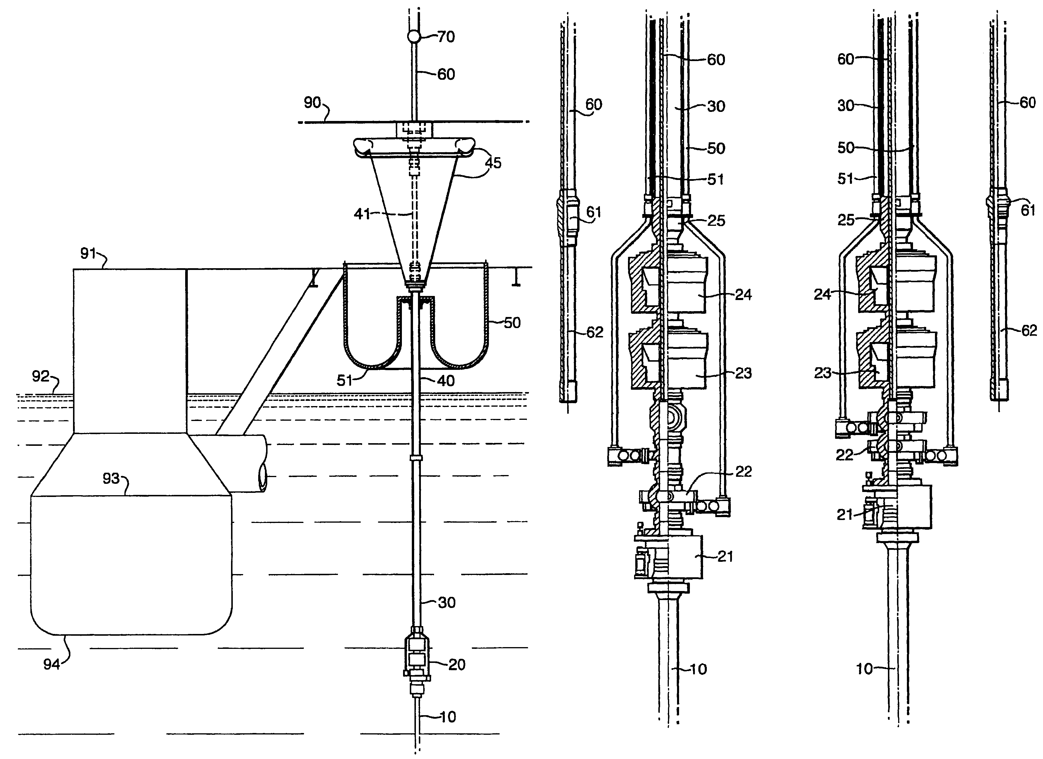
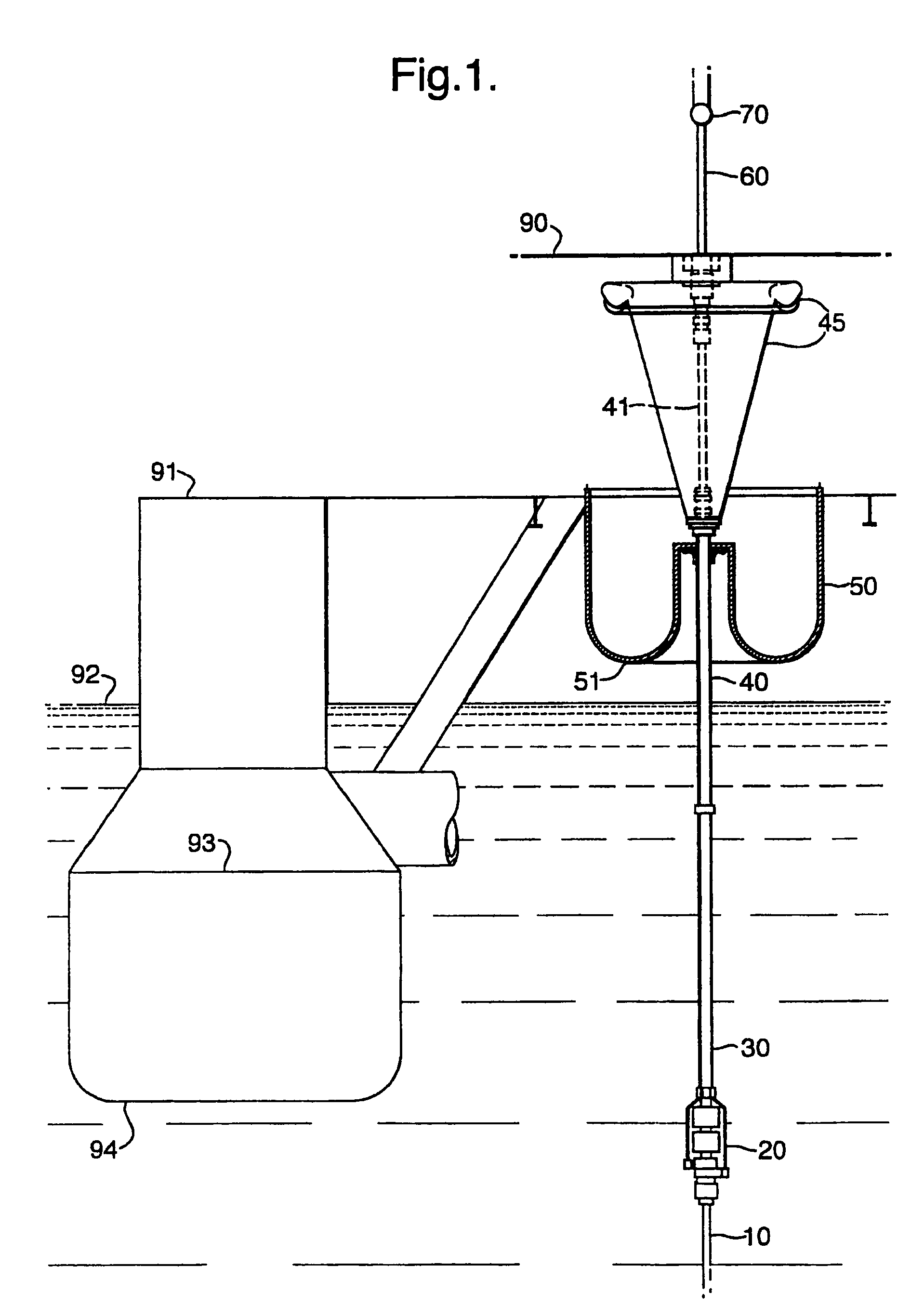
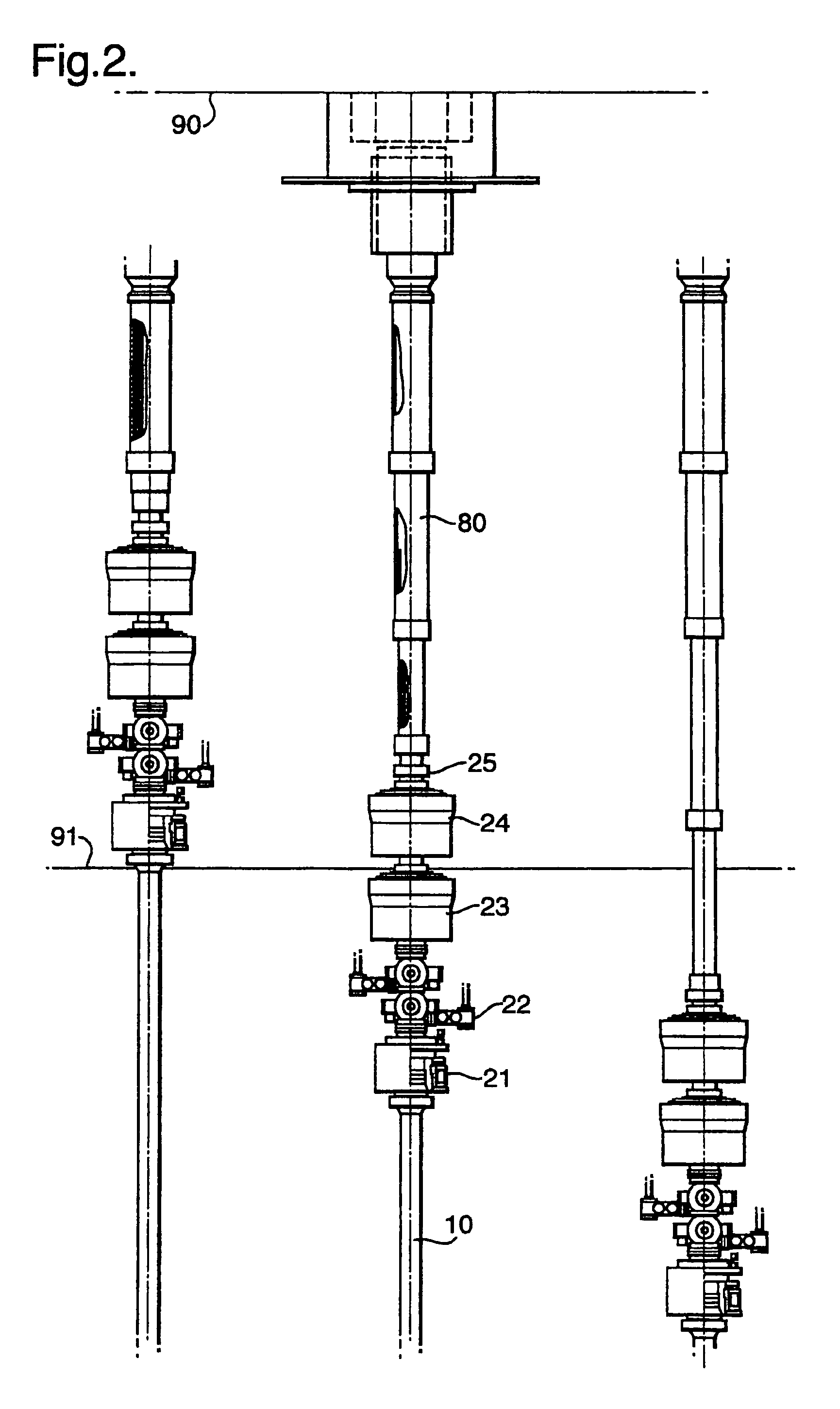
[0020]A system has been developed where the high pressure riser system carries one sub sea BOP stack including a riser disconnect package (RDP) directly above the sub sea BOP stack (not shown on the figure) with a high pressure riser (10) running back to surface, underneath the rigfloor (90). The high pressure riser is terminated in a surface BOP stack (20) above sea level (92)) at cellar deck level (91) which may require a special a special slip joint (80) in FIG. 2 or a sub surface BOP stack just below sea level (92) in FIG. 1. The differences between the surface BOP and the sub surface BOP is caused by the metocean conditions in the geographical areas where the rig is to be operated. The sub surface BOP stack (20) is arranged so that a normal low pressure drilling riser (30) is connected to the sub surface BOP stack (20) and the high pressure riser system (10). The position of the sub surface BOP stack is below Sea Level, and the purpose is to use the low pressure drilling riser ...


PUM


Abstract

An arrangement and method for integrating a high pressure riser sleeve from the upper end of a high pressure drilling and workover riser terminated by an upper BOP close to sea level in one end and by a sub-sea blowout preventer BOP or a low riser package LRP close to the seabed in the lower end. The high pressure riser sleeve being installed, connected and integrated to the high pressure drilling and workover riser and extending up to and above the drill floor, inside a low pressure drilling riser slip joint which is connected to the drilling and workover riser. This relates to offshore drilling and well activities preformed from a floating drilling or workover rig or vessel. Operations can be switched from drilling with jointed drillpipe in a conventional manner, into performing underbalanced wireline and / or coiled tubing activities with full well pressure, much more effectively than with prior art.

Description

BACKGROUND OF THE INVENTION[0001]1. Field of the Invention[0002]The present invention relates to offshore drilling and well activities preformed from a floating drilling or workover rig or vessel.[0003]2. Description of the Related Art[0004]Today, when an offshore sub-sea well is intervened (work performed inside the production tubing below a sub-sea x-mas tree) from a floating vessel, a high pressure workover riser system is used. Such work-over riser systems has been designed with a subsea shut off valve (LRP) and / or a BOP configuration, close to the seabed and includes a riser disconnect package (RDP), to allow for a riser disconnect close to seabed when situations call for it. On the surface, the high pressure riser is terminated in a surface test tree (series of valves) above the rigfloor. To allow for riser tension, the drilling rig's main blocks for lowering and hoisting drillpipe is used to pull tension on the workover riser. Above the surface test tree, the pressure control...

Claims


Application Information

Patent Timeline
Patent Type & Authority Patents(United States)
IPC IPC(8): E21B29/12E21B7/12
CPCE21B17/01E21B17/085
Inventor MOKSVOLD, HARALD
Owner ENHANCED DRILLING
Why Eureka
Try Eureka