Virtually centralized uplink scheduling

a wireless communication system and wireless communication technology, applied in the field of wireless communication system uplink transmission scheduling technology, can solve the problems of ues each interfering with each other, unable to make scheduling decisions for source ues, and affecting the quality of the transmission, so as to reduce the interference of neighbouring cells, and improve the accuracy of call admission and power control mechanisms

Active Publication Date: 2010-02-09
FUJITSU LTD
View PDF24 Cites 25 Cited by
  • Summary
  • Abstract
  • Description
  • Claims
  • Application Information

AI Technical Summary

Benefits of technology

[0009]An advantage of rate scheduling is that, since many UEs are transmitting, interference diversity is maintained, which reduces interference to neighbouring cells. Rate scheduling also provides the advantage that call admission and power control mechanisms are more accurate than for time scheduling. However, rate scheduling suffers from the disadvantage that the Ues will each interfere with each other, since many UEs may be transmitting simultaneously.
[0017]The present invention provides the advantage that uplink scheduling decisions can be made using knowledge of the relative amounts of data in the buffers of the user equipments. This may allow better use to be made of the available resources, which may result in better throughput, lower packet delays, and better quality of service.
[0022]In order for the uplink scheduling to be effective, the relative indicators are preferably updated on a regular basis. However, it may in some circumstances be undesirable for the user equipments to be transmitting indications of the amount of data in their data buffers on a regular basis. For example, if many user equipments are present, or a large amount of data needs to be transmitted in the uplink, the extra transmissions involved in the reporting process may increase the amount of interference or congestion to an unacceptable level. Thus, in a second embodiment, a user equipment sends to the base station an indication of the total amount of data to be sent, and the base station determines the amount of data in the user equipment's data buffer based on the indication of the total amount of data, and the amount of data already received by the base station from that user equipment. This can reduce the number of transmissions involved in the reporting process in the uplink.
[0023]Each user equipment may determine a rate and / or time at which it transmits data to the base station based on the or each relative indicator for that user equipment. For example, a user equipment which receives an relative indicator indicating that it has a relatively full buffer may transmit data to the base station at a higher rate than would otherwise be the case (all other things being equal). On the other hand, a user equipment which receives a relative indicator indicating that it has a relatively empty buffer may transmit data to the base station at a lower rate than would otherwise be the case. In this way, the amount of data in the data buffers of the user equipments can brought into approximate equilibrium, so that all of the data buffers have approximately the same occupancy. This increases the fairness of the system, and may also improve the overall throughput.

Problems solved by technology

However, rate scheduling suffers from the disadvantage that the Ues will each interfere with each other, since many UEs may be transmitting simultaneously.
As a consequence, it is not possible for the source UEs to make scheduling decisions based on the amount of data which the other UEs have to transmit.
For example, in a situation where only one UE has a significant amount of data to transmit (i.e. the other UEs have little data, or there are few active Ues actually present), the UE with a large amount of data still cannot choose to transmit at a high data rate, because it is not aware of the status of the other UEs.
In this situation, the UE with a large amount of data will experience unnecessary delays, because it could in fact have transmitted at a higher data rate.
This may lead to a high level of interference for the entire uplink, and thus a reduction in the quality of service for all UEs.
For example, in a situation in which one UE is just below the assigned threshold and the other UEs are also all below this threshold, the first UE will not still not transmit for a while and will experience an unnecessary delay.

Method used


Image

  • Virtually centralized uplink scheduling
  • Virtually centralized uplink scheduling
  • Virtually centralized uplink scheduling

Examples


first embodiment

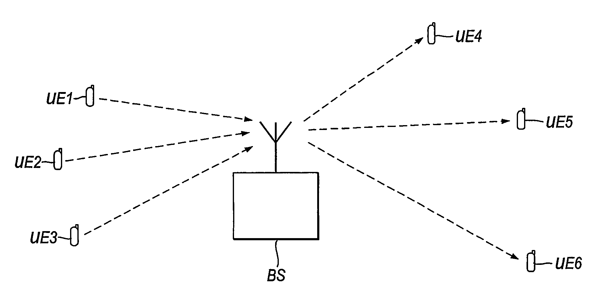
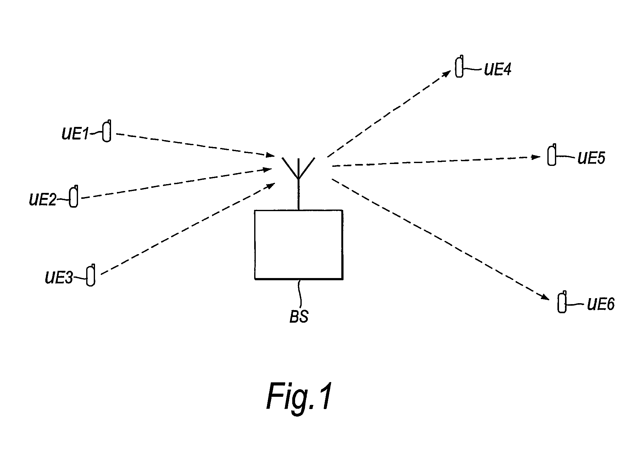
[0075]In the first embodiment of the invention an algorithm is implemented which enables the uplink scheduler to become in effect virtually centralised and non-distributed. This enables the UEs to make better decisions on bit rate or waiting time or format of uplink transmission by having available information about the status of other source UEs in the same cell in the uplink. In this embodiment it is assumed that, as shown in FIG. 1, the base station serves a number of source UEs and destination UEs, and each UE is assigned a packet data buffer.

[0076]Each of the source UEs is grouped into a particular service group depending on the delay tolerance of the data that it is transmitting. The delay tolerance is a measure of the maximum acceptable time for a data packet to reach its destination. For example, video services may have a low delay tolerance of, say, 100 mS, while web services may have a relatively high delay tolerance.

[0077]During each uplink scheduling event, each source U...

second embodiment

[0107]In the first embodiment of the invention a buffer occupancy value is sent from each source user equipment to the base station every scheduling event, which may be every TTI, or every few TTIs. However, in some circumstances even reporting every few TTI may be undesirable because of the channel resources which are occupied. Thus, in a second embodiment of the invention, rather than transmit the buffer occupancy values to the base station at every scheduling event, the base station estimates the buffer occupancy values based on information transmitted to it at the beginning of a call, together with its own knowledge of how many packets it has received from a particular UE.

[0108]In this embodiment it is assumed that each UE is capable of determining the amount of packet data to be sent at the beginning of packet call. Each UE then sends this value to the base station. As communication proceeds further, the base station estimates the amount of data remaining in each UE buffer base...

examples

[0116]An example of the operation of an embodiment of the invention will now be described with reference to FIG. 5. In FIG. 5 a situation is shown in which four source UEs A, B, C and D try to reach their corresponding destination UEs A, B, C and D through the base station. It is assumed that all the UEs experience similar radio channel conditions and SINR (signal to noise and interference ratio). They support streaming real-time service with similar delay tolerances. In FIG. 5, C1 is the distance from average value and C2 is the distance from minimum value. It can be seen that UE A has received C1=49 which means the amount of data in its buffer is well above the average amount of ratios of all UEs. It also receives a C2=75 meaning that it is far away from the UE with minimum buffer data. Looking at its buffer this source UE realizes that its packet data buffer is almost full and it needs to transmit faster to empty its buffer to come down to reach average data levels. Among other U...


PUM


Abstract

A method of scheduling uplink transmissions from a plurality of source user equipments to a base station is disclosed. The method comprises the steps of determining the amount of data in the data buffer of each of the user equipments, comparing the amount of data in the data buffers of the user equipments to obtain, for each user equipment, a relative indicator, the relative indicator indicating how full that user equipment's data buffer is in comparison to the data buffers of the other user equipments, and scheduling uplink transmissions in dependence on the relative indicators. In this way, each user equipment is given some knowledge of the state of the buffer in the other user equipments. The user equipments are therefore able to make more efficient scheduling decisions. This can improve the throughput and give lower packet delivery delays.

Description

CROSS-REFERENCE TO RELATED APPLICATION[0001]This application is the National Stage of International Application No. PCT / GB2004 / 004209, filed Oct. 1, 2004, which claims the benefit under 35 U.S.C. 119 (a-e) of GB 0323246.9 filed Oct. 3, 2003, which is herein incorporated by reference.FIELD OF THE INVENTION[0002]The present invention relates to techniques for scheduling of uplink transmissions in wireless communications systems. The present invention is particularly, but not exclusively, applicable to code division multiple access (CDMA) communications systems such as 3G communication systems.BACKGROUND OF THE INVENTION[0003]FIG. 1 shows parts of a wireless communications system, in which a plurality of source user equipments UE1, UE2, UE3 are in communication with a plurality of destination user equipments UE4, UE5, UE6 via a base station BS. Source UEs UE1, UE2, UE3 transmit data packets in an uplink to the base station BS. Base station BS receives the data packets from the source U...

Claims


Application Information

Patent Timeline
Patent Type & Authority Patents(United States)
IPC IPC(8): H04W4/00H04B7/00H04W72/00H04B7/216H04J13/00H04L12/56H04W72/12
CPCH04W72/1278H04W72/1268H04W72/20H04W72/12H04L47/30
Inventor ABEDI, SAIED
Owner FUJITSU LTD
Why Eureka
Try Eureka