

Low manufacturing cost printed ink liquid level sensors
a liquid level sensor, low manufacturing cost technology, applied in liquid/fluent solid measurement, machines/engines, instruments, etc., can solve the problems of mechanical malfunction, inaccuracy of automobile fuel gauges, and inaccuracy of fuel tanks themselves, so as to save manufacturing costs, accurate readout indications of the amount of remaining fuel in the fuel tank, and low manufacturing cost
- Summary
- Abstract
- Description
- Claims
- Application Information
AI Technical Summary
Benefits of technology
Problems solved by technology
Method used
Image

Examples
Embodiment Construction
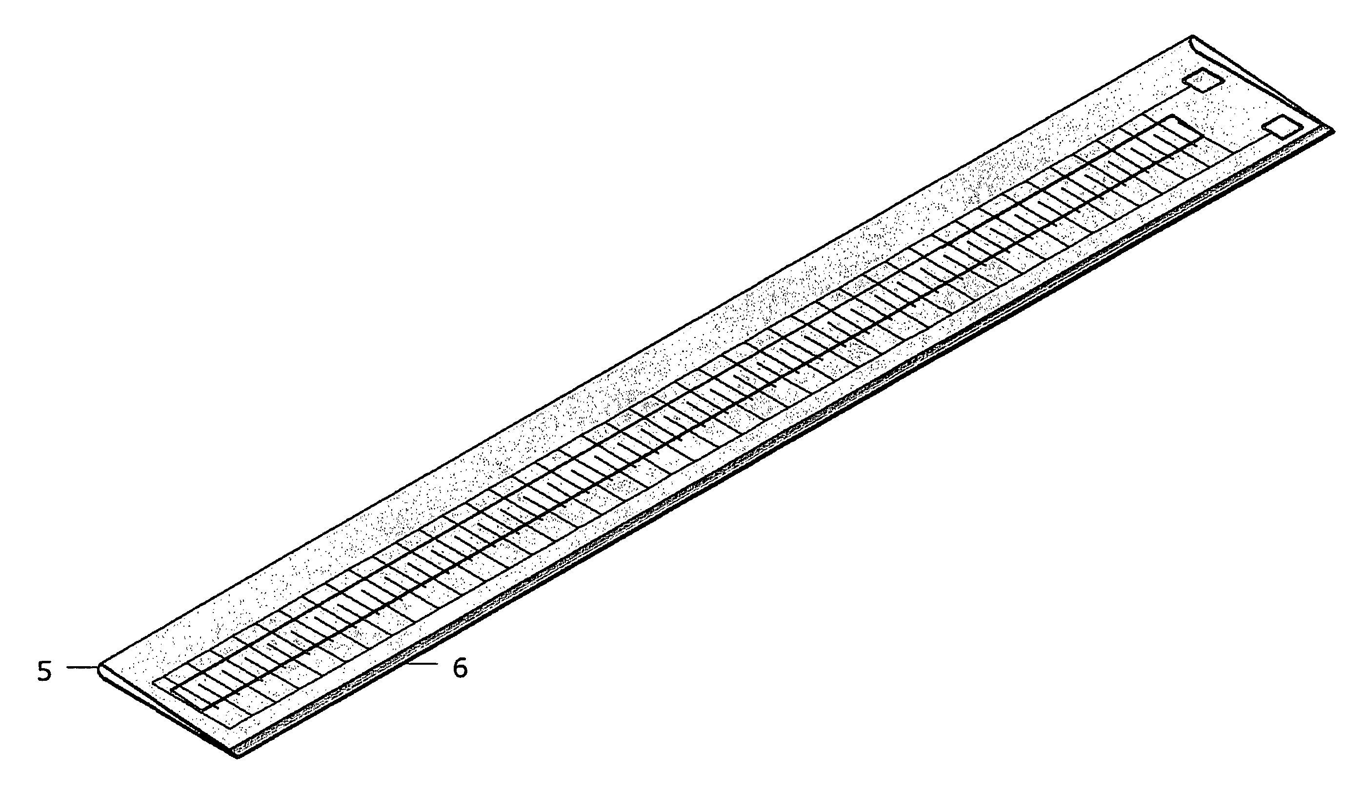
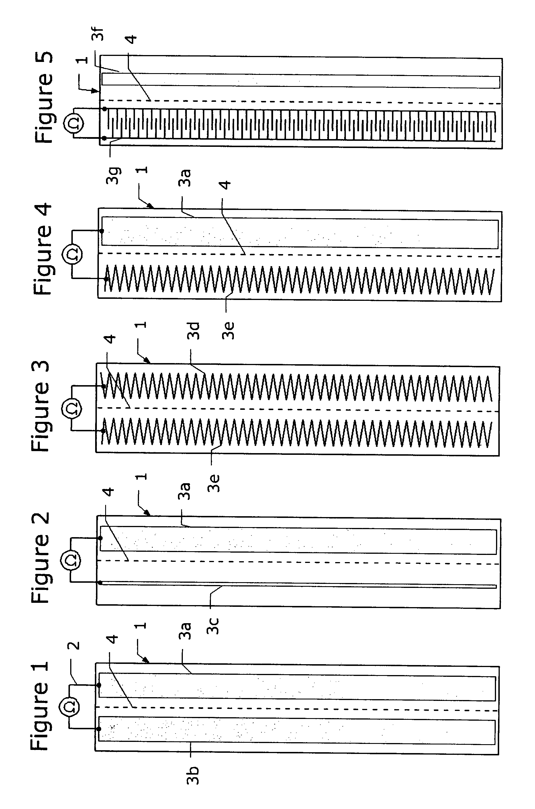
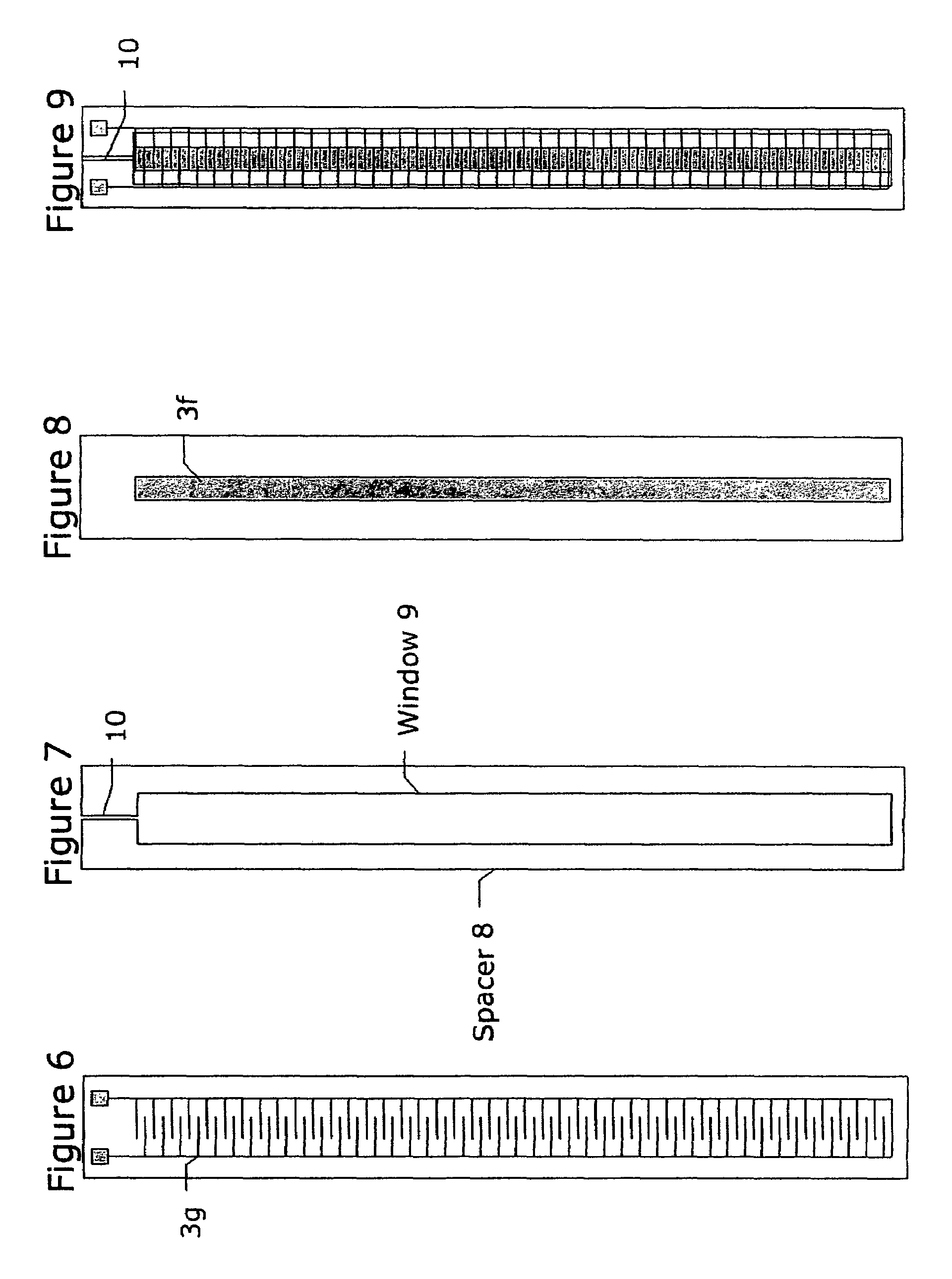
[0008]In order to meet these needs, first and second elongated flexible insulated substrates that face each other are provided, having patterns of resistive liquid level sensor sections thereon along the length of the substrates, each pattern comprising a printable resistive ink upon each substrate preferably of the same resistivity (square ohms), and wherein the patterns can be simultaneously printed upon each substrate to save manufacturing costs. The substrates can be separated by an elongated windowed spacer that couple the longitudinal edges of the facing elongated substrates together with an appropriate adhesive upon the spacer. In another embodiment, the facing substrates can be folded along a central fold line to form a first longitudinal edge and adhesively joined along a second longitudinal edge opposite the first longitudinal edge. The flexibility of the substrates enables the low manufacturing cost liquid level sensors to be positioned anywhere, in any orientation for de...
PUM
 Abstract
Description
Claims
Application Information