Sheet conveying apparatus and image forming apparatus with the sheet conveying apparatus

a conveying apparatus and conveying technology, applied in the direction of electrographic process, transportation and packaging, instruments, etc., can solve the problems of noisy conveyance friction noise, and large conveyance friction noise used to occur, and achieve the effect of lowering the conveyance friction nois

Active Publication Date: 2010-02-16
KYOCERA DOCUMENT SOLUTIONS INC
View PDF7 Cites 11 Cited by
  • Summary
  • Abstract
  • Description
  • Claims
  • Application Information

AI Technical Summary

Benefits of technology

[0008]An object of present invention is to provide a sheet conveying apparatus capable of lowering the conveyance friction noise upon conveying the sheet, and an image forming apparatus with such a sheet conveying apparatus.

Problems solved by technology

In the above-described sheet conveying apparatus, however, there has been a problem that friction between the guide ribs and the sheet to be carried would cause a conveyance friction noise.
More specifically, a large conveyance friction noise used to occur when a pair of conveyance rollers is provided at an upstream side and at a downstream side in the sheet conveyance direction and guide ribs curved into a convex shape toward the sheet conveyance path are provided between the pair of conveyance rollers.
Therefore, the conveyance friction noise tends to be louder.
Also, there may be such a case that a leading edge of some kinds of sheets, e.g., a curled sheet, a sheet having one side printed, a sheet having a cutting burr at its edge, and a thick rigid sheet, may cause a friction noise when it hits the guide ribs.
In recent image forming apparatuses, many of them have a sheet conveyance path which curves with a small curvature in order to downsize the apparatus, such that a guide plate which is placed in such a sheet conveyance path tends to generate the friction noise.
Further, depending on the angle of approach of the leading edge of the sheet to the guide plate, there are such inconveniences that the sheet may be buckled and the leading edge of the sheet may hit projecting side walls of the guide ribs, causing the sheet to skew.

Method used


Image

  • Sheet conveying apparatus and image forming apparatus with the sheet conveying apparatus
  • Sheet conveying apparatus and image forming apparatus with the sheet conveying apparatus
  • Sheet conveying apparatus and image forming apparatus with the sheet conveying apparatus

Examples


first embodiment

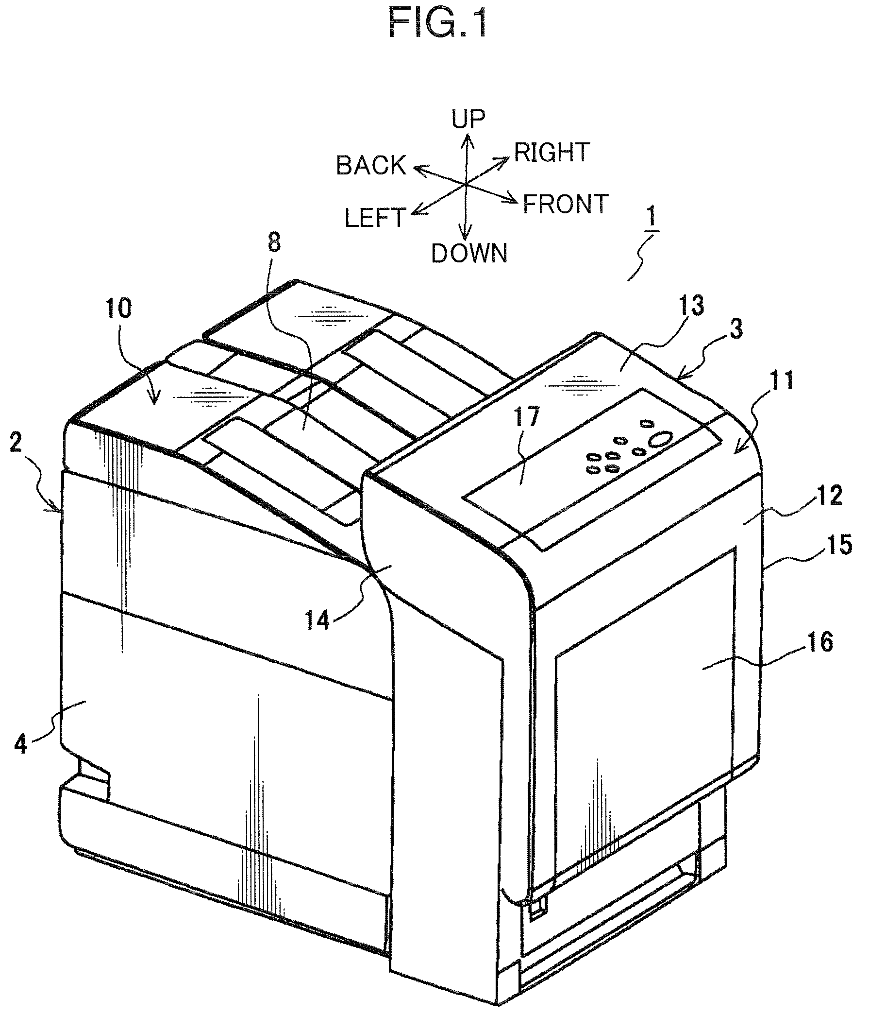
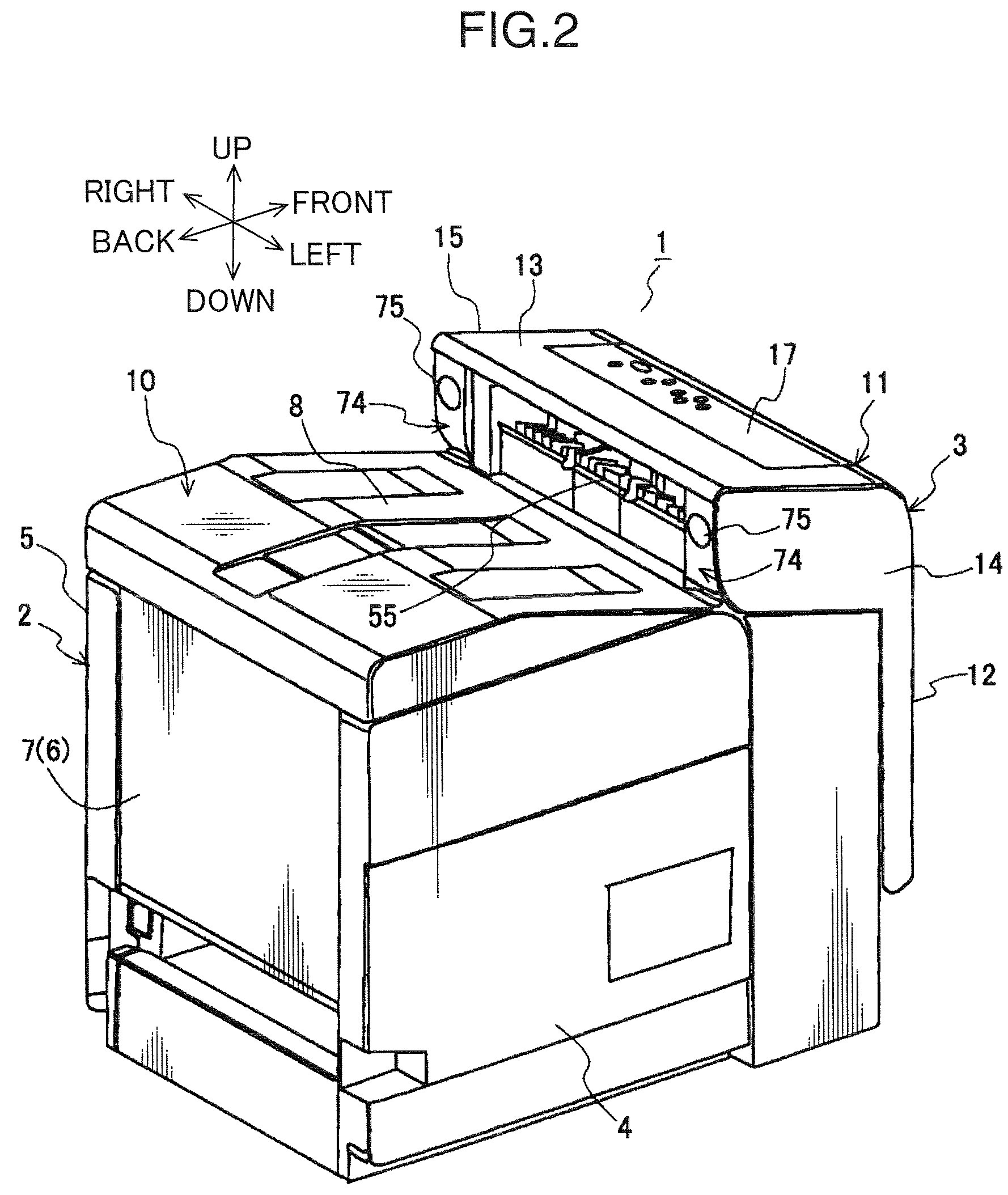
[0022]An image forming apparatus 1 with a sheet conveying apparatus 100 according to a first embodiment will be described below with reference to FIGS. 1 to 3. In FIGS. 1 to 3, arrows show directions of up, down, front, back, left, and right of the image forming apparatus 1. FIG. 1 is a perspective view of the entire image forming apparatus when it is viewed from a diagonally left upward direction on the front side of the apparatus; FIG. 2 is a perspective view of the entire image forming apparatus when it is viewed from a diagonally backward upward direction on the left side of the apparatus; and FIG. 3 illustrates an inside configuration of the image forming apparatus 1 when it is viewed from the left side.

[0023]Examples of the image forming apparatus 1 include a printer, a copying machine, a facsimile machine, and a multifunction device including those functions together; however, a case where the image forming apparatus 1 is a printer will be exemplified in the following descrip...

second embodiment

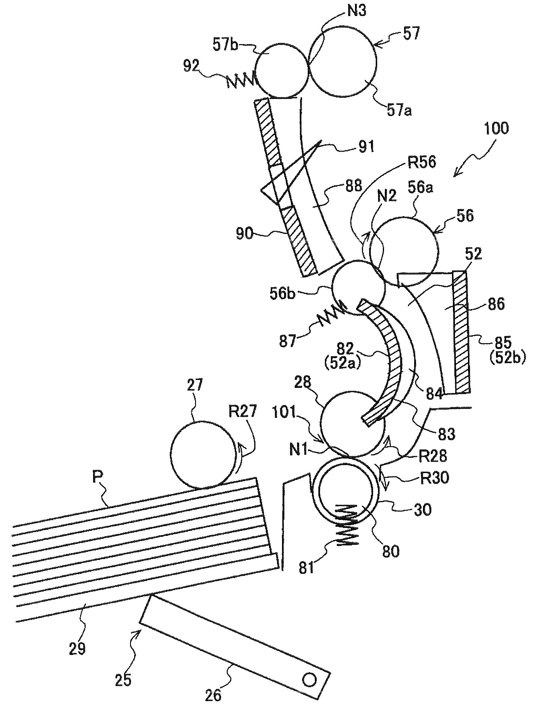
[0082]Now, a second embodiment of the invention will be described below. The second embodiment exemplifies that the present invention is applied to a guide plate to be placed in a sheet conveyance path in a downstream side of the pair of conveyance rollers (first conveyance roller pair). FIG. 8 illustrates an enlarged configuration of a sheet conveying apparatus 100A according to the second embodiment. In FIG. 8, the same components as those in FIG. 4 have the similar reference numbers and thus the explanations thereof will be omitted or simplified here. Although it is omitted in FIG. 4, FIG. 8 illustrates the sheet conveying apparatus 100A including a sheet conveyance path for receiving the manually fed sheets PM supplied from the manual feeding tray 16 as shown in FIGS. 1 and 3.

[0083]The sheet conveying apparatus 100A, similar to the first embodiment, includes the pair of conveyance rollers 101 (delivery roller 28 and retard roller 30) for conveying the sheet P from the sheet cass...


PUM


Abstract

A sheet conveying apparatus includes: a sheet conveyance path designed so as to include nonlinear portions; a first conveyance roller pair which is provided at predetermined positions of the sheet conveyance path and which has a conveyance width capable of nipping and conveying a sheet having the minimum size sheet passing width among sheets to be passed through the sheet conveying apparatus; a guide plate which is placed in a downstream side or an upstream side of the first conveyance roller pair in a sheet conveyance direction and has a curved guide surface; and a plurality of guide ribs which are extended on the guide surface in the sheet conveyance direction and are provided in a sheet passing width direction of the sheet in a region corresponding to the conveyance width of the first conveyance roller pair.

Description

BACKGROUND OF THE INVENTION[0001]1. Field of the Invention[0002]The present invention relates to a sheet conveying apparatus for conveying sheets along a curved guide surface through a pair of conveyance rollers disposed at an upstream side and at a downstream side of the guide surface and an image forming apparatus with the sheet conveying apparatus.[0003]2. Description of the Related Art[0004]In an image forming apparatus such as a printer, a copying machine, a facsimile machine, or the like, a sheet before or after it is provided with an image is conveyed by a sheet conveyance apparatus. Various kinds of sheets are used as a sheet on which an image is provided. For example, art paper having high surface smoothness used in image formation such as a photograph and, to the contrary, recycled paper having low surface smoothness, or the like are used in addition to copying paper in general use. Also, each kind of paper includes different sizes from a larger size to a smaller size, or ...

Claims


Application Information

Patent Timeline
Patent Type & Authority Patents(United States)
IPC IPC(8): B65H5/00
CPCB65H5/062B65H5/38G03G15/6529B65H2404/14B65H2404/513B65H2404/6111B65H2801/06G03G2215/00675B65H2220/09
Inventor DOYO, HIDEAKI
Owner KYOCERA DOCUMENT SOLUTIONS INC
Why Eureka
Try Eureka