Eureka AIR delivers breakthrough ideas for toughest innovation challenges, trusted by R&D personnel around the world.

Conveyor apparatus having a twice-twisted belt and a floating-tension pulley

a conveyor and belt technology, applied in the direction of conveyors, conveyor parts, article feeders, etc., can solve the problems of non-negligent maintenance costs and detriment to the proper operation of stackers, and achieve the effect of reducing the friction noise in the conveyor apparatus and lengthening over tim

Inactive Publication Date: 2008-10-28
SOLYSTIC
View PDF7 Cites 8 Cited by
  • Summary
  • Abstract
  • Description
  • Claims
  • Application Information

AI Technical Summary

Benefits of technology

[0007]The floating pulley of the invention thus has an axis of rotation that is mounted to be floating in three-dimensional space. With this arrangement, it is thus simple for the twice-twisted belt to be stabilized simply in the vertical plane by self-centering with, in addition, the twice-twisted belt being tensioned dynamically, which compensates for it lengthening over time.
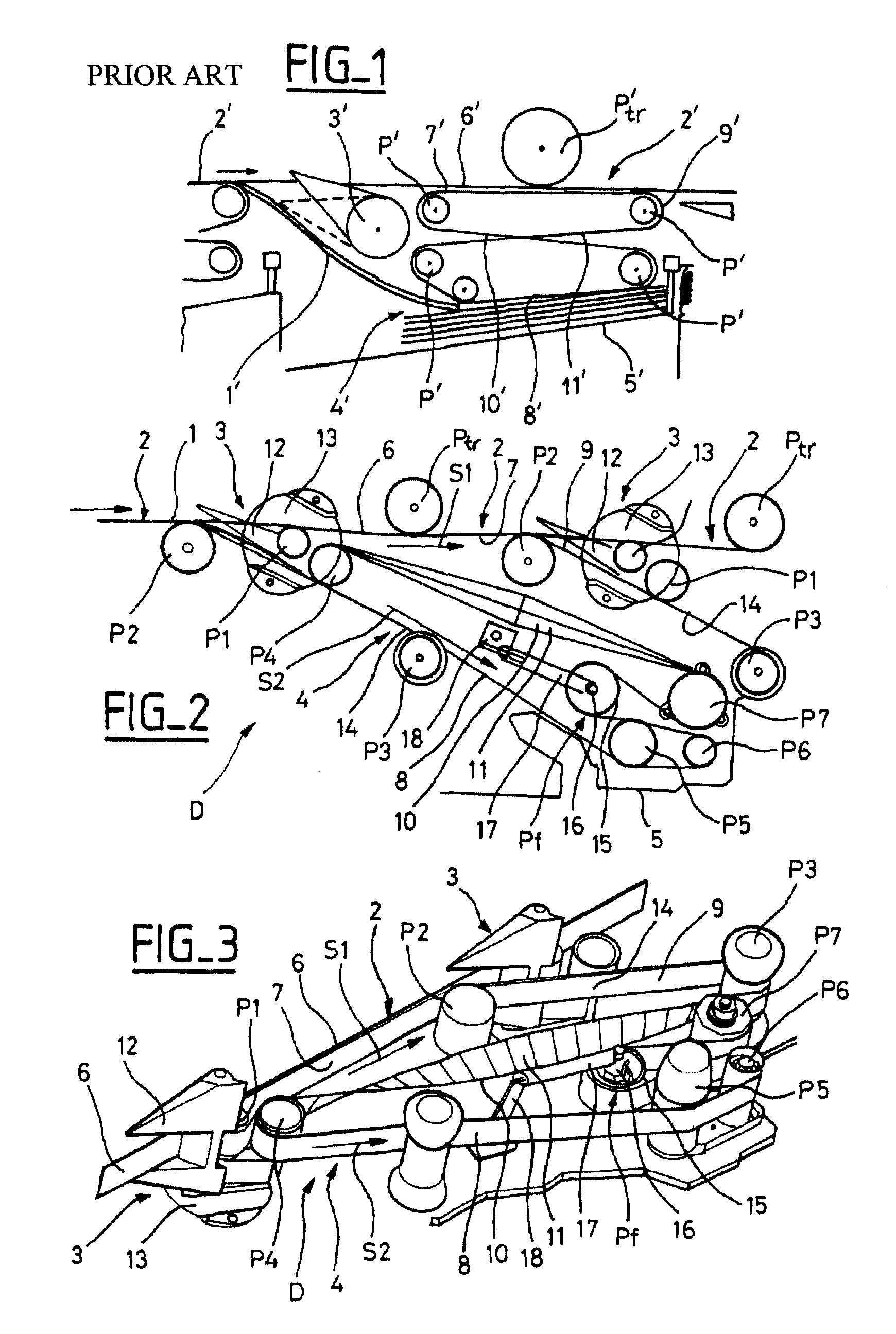
[0008]In the conveyor apparatus of the invention, the twice-twisted belt follows a figure-of-eight shaped path having two loops, and said belt has two twisted belt segments that are superposed where the two loops cross over, said two belt segments being in contact with each other over their entire length between two deflector pulleys. With this arrangement of the twice-twisted belt, friction noise in the conveyor apparatus is reduced considerably.

Problems solved by technology

In such conveyor apparatus, it has been observed that the path of the belt 9′ can vary in the vertical plane, which is detrimental to proper operation of the stackers of the sorting machine.
Such untimely displacements of the belt 9′ are presently eliminated by regularly and manually re-centering the belt 9‘on the pulleys P’, which gives rise to non-negligible maintenance costs.

Method used


Image

  • Conveyor apparatus having a twice-twisted belt and a floating-tension pulley
  • Conveyor apparatus having a twice-twisted belt and a floating-tension pulley
  • Conveyor apparatus having a twice-twisted belt and a floating-tension pulley

Examples


Embodiment Construction

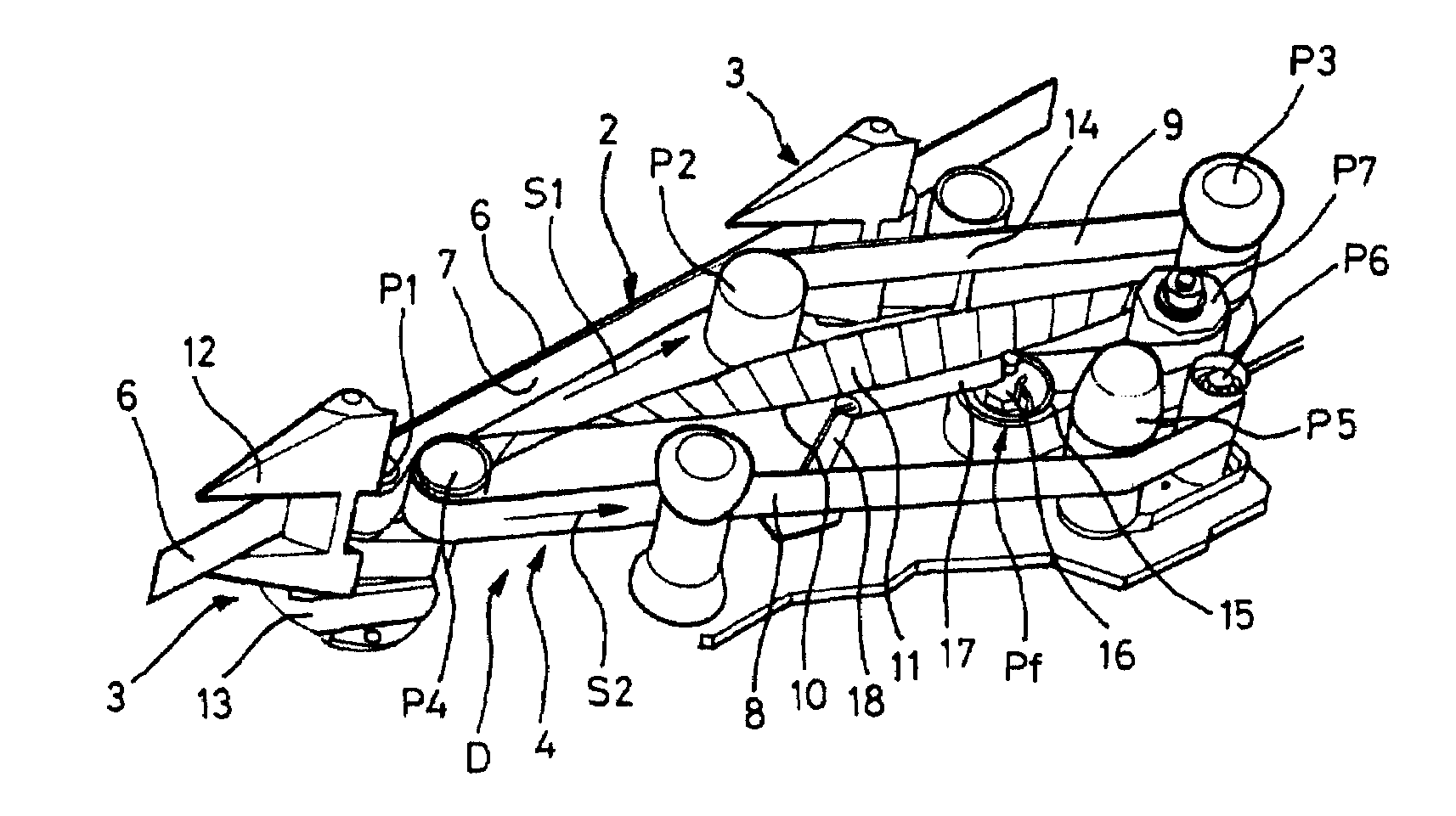
[0016]As shown in FIG. 2, a mail item 1, in particular a letter or any other flat postal item, moved by a main conveyor 2 of the conveyor apparatus D is switched by a switching flap 3 towards a stacker conveyor 4 in order to be routed towards a stacker 3 at a sorting outlet of a postal sorting machine. The switching flap 3, which can be seen more clearly in FIG. 3, is constituted by a fork-shaped finger 12 mounted to pivot on a soleplate 13 provided with a guide channel for guiding the foot of the mail item.

[0017]The main conveyor 2 comprises a transport belt 6 driven by friction by a set of motor-driven pulleys Ptr distributed along the sorting outlets of the sorting machine. At each sorting outlet, the belt 6 co-operates by nipping with a first rectilinear segment 7 (forming a main belt) of a twice-twisted belt 9 that is engaged around deflector pulleys P1 and P2 disposed in alignment along the belt 6. As can be seen in FIG. 2, a switching flap 3 is interposed between every two co...


PUM

PropertyMeasurementUnit
lengthaaaaaaaaaa
frictionaaaaaaaaaa
speedsaaaaaaaaaa

Abstract

A conveyor apparatus including a main conveyor by which mail items are routed by being nipped between a transport belt and a main belt, and a secondary conveyor towards which the mail items are routed, after switching, along a secondary belt. The main and secondary belts performing the main conveying and the secondary conveying functions are constituted by a single, common belt that is twisted twice. The twice-twisted belt is engaged over a tensioner pulley that is a floating pulley.

Description

BACKGROUND OF THE INVENTION[0001]The invention relates to conveyor apparatus comprising a main conveyor by which mail items are routed by being nipped between a transport belt and a main belt, and a secondary conveyor towards which the mail items are routed, after switching, along a secondary belt, said main and said secondary belts performing the main conveying and the secondary conveying functions being constituted by a single, common belt that is twisted twice.[0002]Such conveyor apparatus is known from Patent Document FR-2 555 974. It is used for switching mail items and stacking them in the sorting outlets of a postal sorting machine. In that known conveyor apparatus which is shown very diagrammatically in FIG. 1, a mail item 1′ is transported by a main conveyor 2′ and is switched by a switching flap 3′ towards a stacker conveyor 4′ of a sorting outlet stacker 5′ of a postal sorting machine. The main conveyor 2′ is constituted by a transport belt 6′ and by a main belt 7′ that e...

Claims


Application Information

Patent Timeline
Patent Type & Authority Patents(United States)
IPC IPC(8): B65H43/04B65G23/44B65H29/12B65H29/58B65H31/10B65H31/28
CPCB65H31/06B65H2301/321B65H2404/261B65H2404/2613B65H2701/1916
Inventor EYRAUD, FABRICERIEU, JEANCHIFFLET, RAYMOND
Owner SOLYSTIC
Why Eureka
Eureka Blog
Learn More