Energy effective switching power supply apparatus and an energy effective method thereof

a power supply apparatus and energy-saving technology, applied in the direction of power conversion systems, dc-dc conversion, instruments, etc., can solve the problems of unnecessary power consumption and power loss of switching, and achieve the effect of preventing unnecessary power consumption and damages caused by overvoltag

Active Publication Date: 2010-02-16
HEWLETT PACKARD DEV CO LP
View PDF16 Cites 18 Cited by
  • Summary
  • Abstract
  • Description
  • Claims
  • Application Information

AI Technical Summary

Benefits of technology

[0015]The present general inventive concept provides an energy effective switching power supply apparatus and an energy effective method thereof to adjust a switching frequency of a PWM-IC (Pulse Width Modulation-integrated Circuit) in order to prevent unnecessary power consumption and damages caused by overvoltage.
[0021]The foregoing and / or other aspects of the present general inventive concept may also be achieved by providing a power supply apparatus, including a transformer to receive an input voltage at a first coil and to output at least one output voltage on at least one second coil, a controller to switch the transformer ON and OFF at two or more operating frequencies to regulate the at least one output voltage according to a feedback signal, and at least one power output part to receive the at least one output voltage from the transformer, to output at least one output DC voltage, and to provide a first feedback signal to the controller to decrease the frequency with which the transformer is switched when the at least one output DC voltage is greater than a reference voltage level.

Problems solved by technology

Likewise, the conventional switching power supply apparatus switches the transistor TR1 ON or OFF at a uniform frequency all the time, regardless of changes of the first and second output voltages Va and Vb, respectively, and accordingly, a switching loss is incurred and unnecessary power consumption occurs.

Method used


Image

  • Energy effective switching power supply apparatus and an energy effective method thereof
  • Energy effective switching power supply apparatus and an energy effective method thereof
  • Energy effective switching power supply apparatus and an energy effective method thereof

Examples


Embodiment Construction

[0032]Reference will now be made in detail to the embodiments of the present general inventive concept, examples of which are illustrated in the accompanying drawings, wherein like reference numerals refer to the like elements throughout. The embodiments are described below in order to explain the present general inventive concept by referring to the figures.

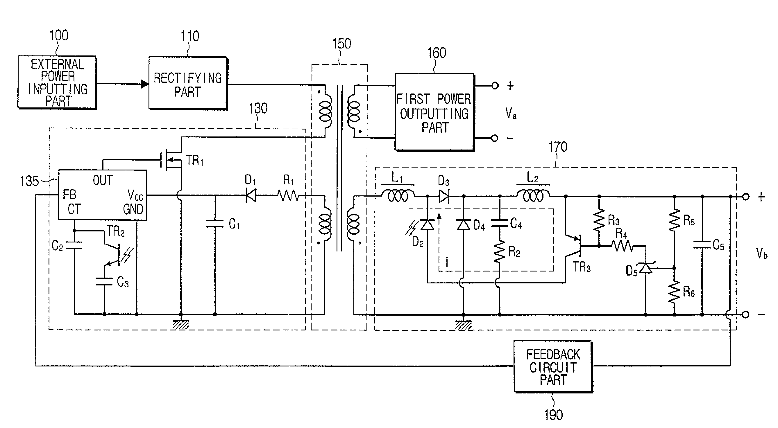
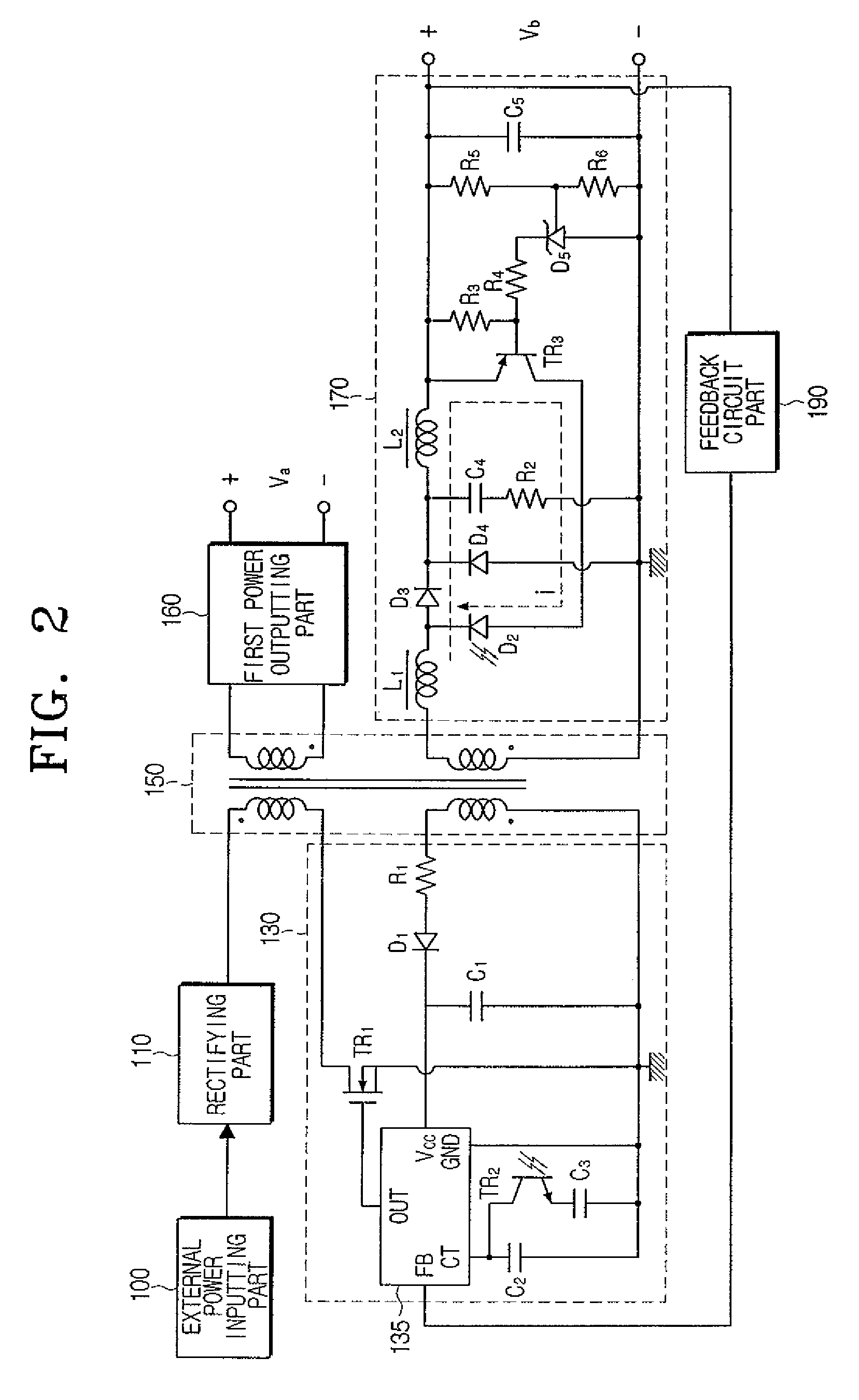
[0033]FIG. 2 illustrates a switching power supply apparatus according to an embodiment of the present general inventive concept.

[0034]Referring to FIG. 2, the switching power supply apparatus includes an external power inputting part 100, a rectifying part 110, a switching controlling part 130, a power transforming part 150, a first power outputting part 160, a second power outputting part 170, and a feedback circuit part 190.

[0035]The external power inputting part 100 receives an AC (Alternating Current) power from an external power supply (not shown) as an input.

[0036]The rectifying part 110 rectifies the input AC power and ou...


PUM


Abstract

An energy effective switching power supply apparatus and an energy effective method thereof. The energy effective switching power supply apparatus includes a power transforming part having first and second coils to induce a voltage to the second coil using interactions between the first and the second coils with respect to the input voltage, a power outputting part to output a sensing signal when it is determined that a first DC voltage output by rectifying and smoothing the voltage induced to the second coil is greater than or equal to a reference voltage level, and a switching controlling part to adjust a switching frequency of a switching device to interrupt a current flowing in the first coil of the power transforming part when the sensing signal is received. Accordingly, a switching loss is controlled and an energy loss is reduced.

Description

CROSS-REFERENCE TO RELATED APPLICATIONS[0001]This application claims the benefit under 35 U.S.C. § 119(a) of Korean Patent Application No. 2005-89890, filed Sep. 27, 2005, in the Korean Intellectual Property Office, the entire contents of which are incorporated herein by reference.BACKGROUND OF THE INVENTION[0002]1. Field of the Invention[0003]The present general inventive concept relates to an energy effective switching power supply apparatus and an energy effective method thereof. More particularly, the present general inventive concept relates to an energy effective switching power supply apparatus and an energy effective method thereof that saves energy by improving power efficiencies of an SMPS (Switching Mode Power Supply) used as a switching power apparatus in electronics appliances.[0004]2. Description of the Related Art[0005]Generally, an SMPS (Switching Mode Power Supply) is used as a switching power supply apparatus in an image forming apparatus, such as a printer. The SM...

Claims


Application Information

Patent Timeline
Patent Type & Authority Patents(United States)
IPC IPC(8): H02M3/335H02H7/122
CPCH02M3/33507H02M3/33561H02M2001/0006H02M1/0006H02M3/28
Inventor NA, TAE-KWON
Owner HEWLETT PACKARD DEV CO LP
Why Eureka
Try Eureka