Measuring device with extensible cord and method

a technology of measuring device and extensible cord, which is applied in the direction of measuring tape, mechanical measuring arrangement, instruments, etc., can solve the problems of inability to meet the needs of the user, etc., to achieve the effect of improving reducing the accuracy of the measurement, and reducing the cost of the devi

Active Publication Date: 2010-02-23
DELTA II I P TRUST
View PDF11 Cites 19 Cited by
  • Summary
  • Abstract
  • Description
  • Claims
  • Application Information

AI Technical Summary

Problems solved by technology

Conventional devices and methods for measuring, for example a room for remodeling, are slow, labor intensive and not very inaccurate.
These devices are extremely expensive and have limited accuracy on many surfaces.
Their accuracy is especially diminished where accuracy is most desired, such as in corners and on curved surfaces.

Method used


Image

  • Measuring device with extensible cord and method
  • Measuring device with extensible cord and method
  • Measuring device with extensible cord and method

Examples


second embodiment

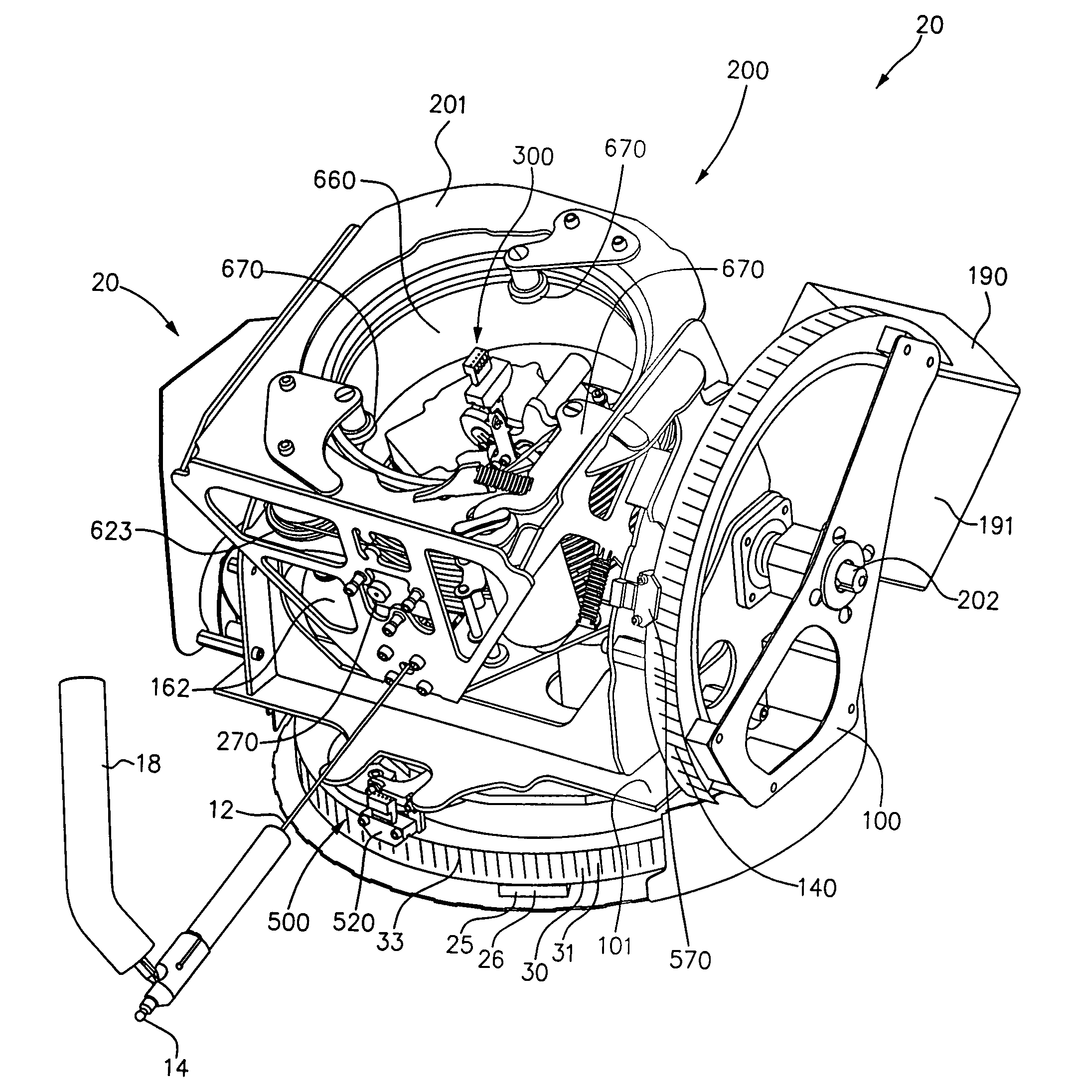
[0089]FIG. 9 is a perspective schematic of the cable angular displacement sensor 300 in the form of proximity or contact sensors, such as contact sensors 380 mounted to frame 201. Cable 12 is shown in alignment position 305.

[0090]A first pair 380A of contact sensors 381A, 381B are equally spaced on opposite sides of cable 12 for detecting angular displacement of cable 12 about a first contact sensor axis perpendicular to a midline between first sensors 380A. A second pair 380B of contact sensors 381C, 381D are equally spaced on opposite sides of cable 12 for detecting angular displacement of cable 12 about a second contact sensor axis perpendicular to a midline between second sensors 380B. If cable 12 is angularly displaced so as to touch sensor 381A, sensor 381A produces a signal on line 308C1 indicating rotation is required about the first contact sensor axis in a first direction. If cable 12 touches sensor 381B, sensor 381B produces a signal on line 308C2 indicating rotation is r...

third embodiment

[0092]FIG. 10 is a perspective schematic of the cable angular displacement sensor 300 in the form of optical sensors 385 mounted to frame 201 for detecting movement of cable 12 from the alignment position 305. Cable 12 is shown in alignment position 305.

[0093]In the exemplary embodiment, each optical sensor 385 includes a light source 386, some focusing lenses 387, and a light sensor 388.

[0094]A pitch optical sensor 385A includes light source 386A that emits light and is disposed on one side of cable 12 and a light sensor 388A for receiving the emitted light is disposed on the other side of cable 12. Light sensor 388A may include a CCD array 389A or other light detector as is well known. One or more lenses, such as lenses 387, may be used to focus or magnify the light for accurate reading. Sensor 388A detects when the shadow of cable 12 moves up or down and produces a signal, such as on line 309D, indicative thereof for directing pitch servoed motor 162 to move pitch carriage 200 so...

fourth embodiment

[0098]FIG. 11 is a perspective schematic of the cable angular displacement sensor 300 in the form of a magnetic or electromagnetic sensor 390. A pitch electromagnetic sensor 390A detects the proximity of cable 12 and, when cable 12 moves up or down, produces a signal, such as on line 309E, indicative thereof for directing pitch servoed motor 162 to move pitch carriage 200 so as to return cable 12 to alignment position 305. A turn optical sensor 390B detects the proximity of cable 12 and, when 12 moves left or right, and produces a signal, such as on line 308E, indicative thereof for directing turn servoed motor 122 to move turn carriage 100 so as to return cable 12 to alignment position 305.

[0099]Magnetic sensors could also be used to detect the proximity of cable. In the exemplary embodiment, the output of sensors 390 corresponds directly to movement in θ and φ. However, other axes may be used and translated into movement in θ and φ.


PUM


Abstract

A measuring device generally comprises a base unit housing an extensible cable; the cable including a free end for placement by a user at a point being measured. The base unit, placed in line of sight of the point, includes: a base; a first carriage rotationally attached to the base about a turn axis; and a second carriage rotationally attached to the first carriage about a pitch axis. Servoed motors rotate the carriages to align them with cable path to the point. The turn angle, the pitch angle and the cable length are measured to determine the point's location. A plurality of points determines a surface. The user uses a programmed PDA with a radio to communicate with the base unit.

Description

FIELD OF THE INVENTION[0001]This invention relates in general to measuring devices and more specifically involves a measuring device with an extensible cord having a free end, the cord free end for placement on a point to measure its location.BACKGROUND OF THE INVENTION[0002]Conventional devices and methods for measuring, for example a room for remodeling, are slow, labor intensive and not very inaccurate. Usually, two persons take measurements with tape measure and protractors.[0003]The most modern methods use laser measuring devices. These devices are extremely expensive and have limited accuracy on many surfaces. Their accuracy is especially diminished where accuracy is most desired, such as in corners and on curved surfaces.[0004]Several devices measure a three-dimensional object by placing a probe on multiple points on the object and determining the relative positions of the points from their positions relative to the probe's base unit.[0005]For example, U.S. Pat. No. 4,703,443...

Claims


Application Information

Patent Timeline
Patent Type & Authority Patents(United States)
IPC IPC(8): G01B3/10
CPCE04F21/00E04F21/0076G01B3/11G01B5/004G01B5/008G01B7/30G01B11/26G01B21/04G01B21/22G01C15/002G01B7/026Y10S33/21
Inventor SWANSON, DAVID W.SWANSON, WILLIAM ROBERT
Owner DELTA II I P TRUST
Why Eureka
Try Eureka