Delivery catheter for ribbon-type prosthesis and methods of use

a ribbon-type prosthesis and catheter technology, applied in the field of catheter delivery, can solve the problems of large delivery profile, unsuitable stents for use in smaller vessels, and poor placement effect, and achieve the effect of reducing the complexity of the procedur

Inactive Publication Date: 2010-02-23
NOVOSTENT CORP
View PDF11 Cites 56 Cited by
  • Summary
  • Abstract
  • Description
  • Claims
  • Application Information

AI Technical Summary

Benefits of technology

[0015]It is another object of this invention to provide means for anchoring a distal end of a delivery catheter to the vessel wall, prior to deployment of a radially expandable anchor portion of the stent, so as to prevent inadvertent axial movement of the delivery catheter during deployment of the stent.
[0016]It is a furthe

Problems solved by technology

Such stents commonly have several drawbacks, for example, the stents may experience large length changes during expansion (referred to as “foreshortening”) and may shift within the vessel prior to engaging the vessel wall, resulting in improper placement.
Additionally, many self-expanding stents have relatively large delivery profiles because the configuration of their struts limits further compression of the stent.
Accordingly, such stents may not be suitable for use in smaller vessels, such as cerebral vessels and coronary arteries.
Other drawbacks associated with the use of coils or stents in the treatment of aneurysms is that the devices, when deployed, may have a tendency to straighten or otherwise remodel a delicate cerebral vessel, which may cause further adverse consequences.
Moreover, such devices may not adequately reduce blood flow from the cerebral vessel into the sac of the aneurysm, which may increase the likelihood of rupture.
Generally, if a great

Method used


Image

  • Delivery catheter for ribbon-type prosthesis and methods of use
  • Delivery catheter for ribbon-type prosthesis and methods of use
  • Delivery catheter for ribbon-type prosthesis and methods of use

Examples


Embodiment Construction

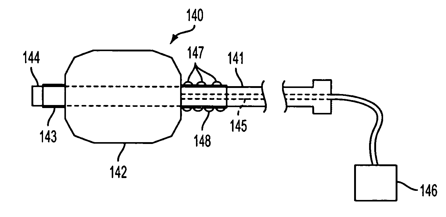
[0033]The present invention is directed to a delivery catheter for use with an implantable vascular prosthesis configured for use in a wide range of applications, such as treating aneurysms, maintaining patency in a vessel, and allowing for the controlled delivery of therapeutic agents to a vessel wall. The delivery catheter of the present invention is designed for use in delivering a vascular prosthesis having a helical ribbon portion joined, at its distal end, to a radially self-expanding anchor portion. The delivery catheter provides enhanced accuracy in delivering the stent by reducing the risk of bunching of the stent and inadvertent axial movement of the delivery catheter during stent deployment. In addition, the delivery catheter may optionally include an angioplasty balloon to perform angioplasty, thus reducing the number of equipment exchanges required to perform an interventional procedure.

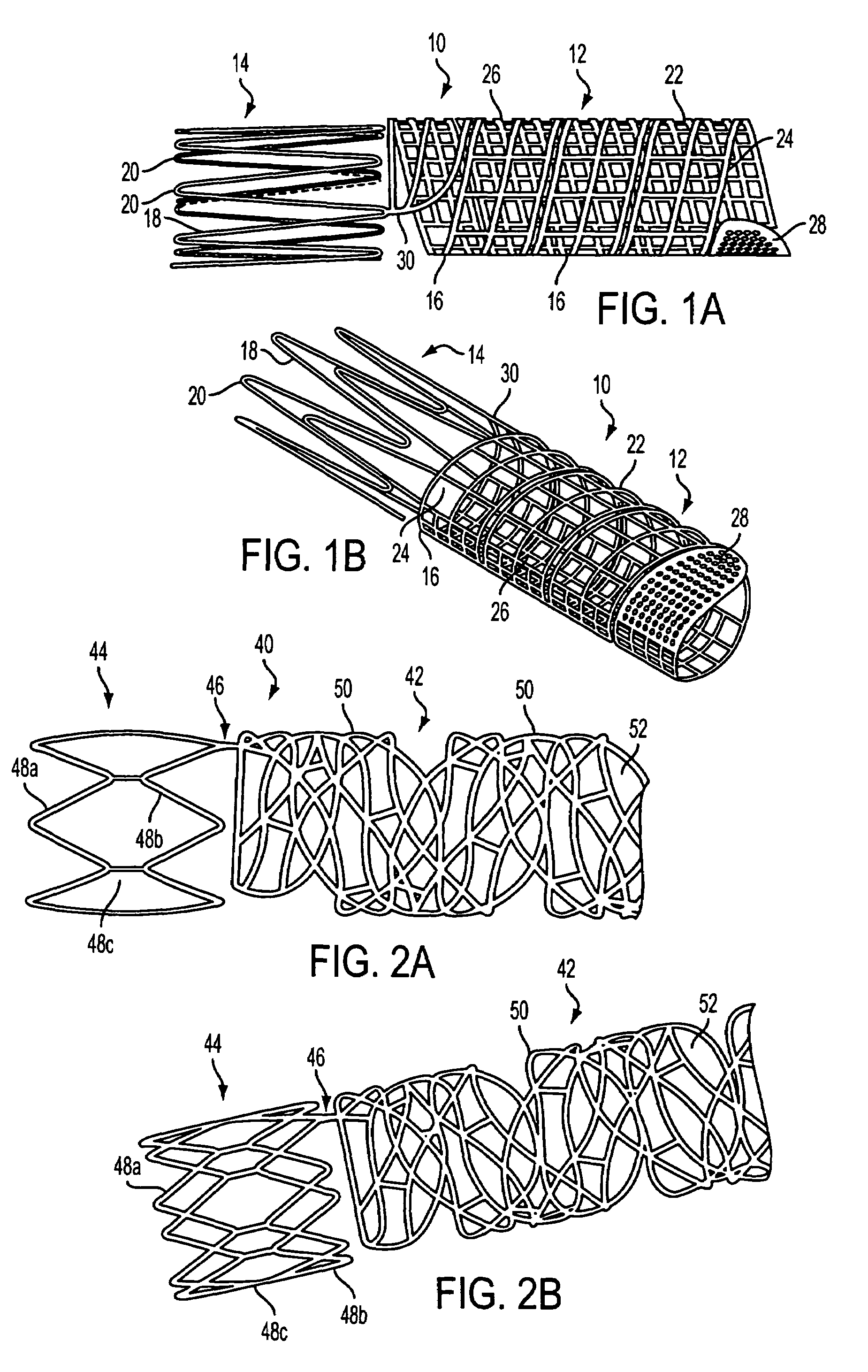
[0034]Referring to FIGS. 1A and 1B, a first embodiment of a vascular prosthesis suit...


PUM


Abstract

The present invention is directed to a delivery catheter for use in deploying a vascular prosthesis having a self-expanding radial distal section joined to a helical section for use in a wide range of interventional applications. The delivery catheter comprises an elongated member having a balloon disposed adjacent to a distal end of the member, means for engaging the distal section of the vascular prosthesis against axial translation, and a sheath that restrains the vascular prosthesis against the elongated member during transluminal delivery. The balloon also may be used to perform angioplasty of a stenosis located within the vessel prior to deployment of the vascular prosthesis. Methods of using the delivery catheter of the present invention also are provided.

Description

REFERENCE TO RELATED APPLICATIONS[0001]This application is a continuation-in-part of U.S. patent application Ser. No. 10 / 342,427, filed Jan. 13, 2003, which claims priority from U.S. provisional patent application Ser. No. 60 / 436,516, filed Dec. 24, 2002.FIELD OF THE INVENTION[0002]The present invention relates to a delivery catheter, and methods of use, for an implantable vascular ribbon-type prosthesis having a helical section and at least one anchor section, wherein the delivery system reduces stent axial movement during deployment, both with respect to the vessel and the delivery catheter.BACKGROUND OF THE INVENTION[0003]Today there are a wide range of intravascular prostheses on the market for use in the treatment of aneurysms, stenoses, and other vascular irregularities. Balloon expandable and self-expanding stents are well known for restoring patency in a stenosed vessel, e.g., after an angioplasty procedure, and the use of coils and stents are known techniques for treating a...

Claims


Application Information

Patent Timeline
IPC IPC(8): A61F2/06A61F11/00A61F2/00A61F2/82A61F2/88
CPCA61F2/88A61F2/95A61F2/966A61F2/91A61F2230/0054A61F2002/828A61F2250/0068
Inventor HOGENDIJK, MICHAELTHOMPSON, TODDALEXANDER, MILES
Owner NOVOSTENT CORP
Why Eureka
Try Eureka