Motor having shaft members

a technology of motor shaft and shaft member, which is applied in the direction of instruments, magnetic circuit shape/form/construction, roofs, etc., can solve the problems of abnormal noise, potential difference caused by unbalanced voltage applied to the motor, and problem of axial electric current caused by a potential difference in the motor

Inactive Publication Date: 2010-02-23
NIDEC SHIBAURA CORP
View PDF8 Cites 3 Cited by
  • Summary
  • Abstract
  • Description
  • Claims
  • Application Information

AI Technical Summary

Benefits of technology

[0008]According to preferred embodiments of the present invention, a motor is provided. In the motor, a plurality of shaft members forming together a shaft coaxial with a rotation axis of the motor are connected to each other via a shaft connecting member which can electrically insulate the shaft members from each other. That is, the shaft members are not in direct contact with each other. The shaft connecting member prevents an axial electric current from flowing between the shaft members.
[0009]Instead of the shaft connecting member, a rotor magnet containing ferrite powders may be interposed axially between the shaft members. Since the rotor magnet containing ferrite powders has a high electrically insulating property, i.e., a high electric resistance, the axial electric current can be reduced well.

Problems solved by technology

In motors driven by a higher voltage of 100 volts or higher and controlled by PWM (pulse width modulation) control, an axial electric current caused by a potential difference in the motor has been a problem for some time.
The potential difference is produced by an unbalanced voltage applied to the motor, unevenness of a gap between a stator and a magnet, or a voltage change at a neutral point in PWM control, for example.
Such a rough surface plays a role in causing abnormal noise.

Method used


Image

  • Motor having shaft members
  • Motor having shaft members
  • Motor having shaft members

Examples


Embodiment Construction

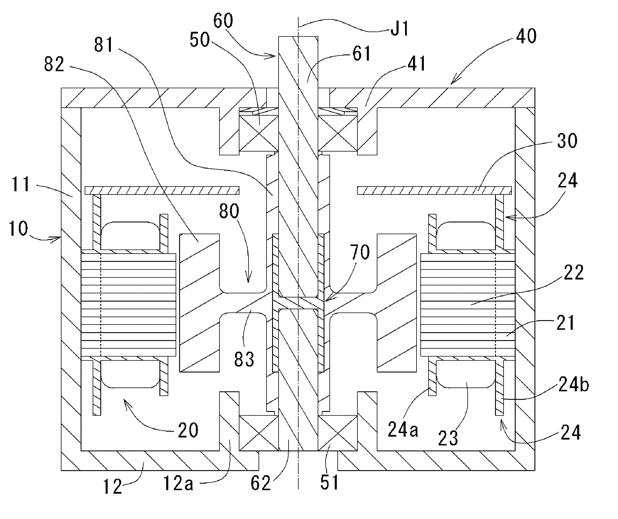
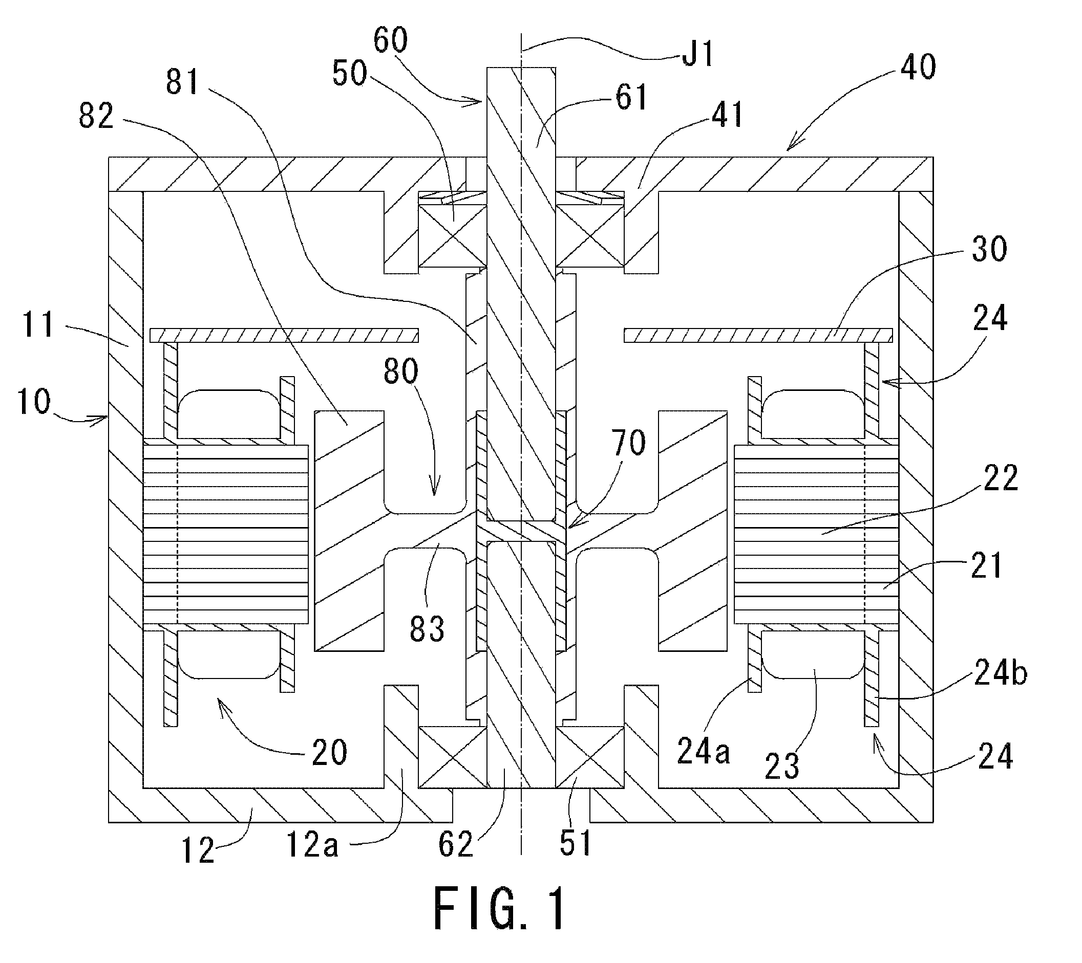
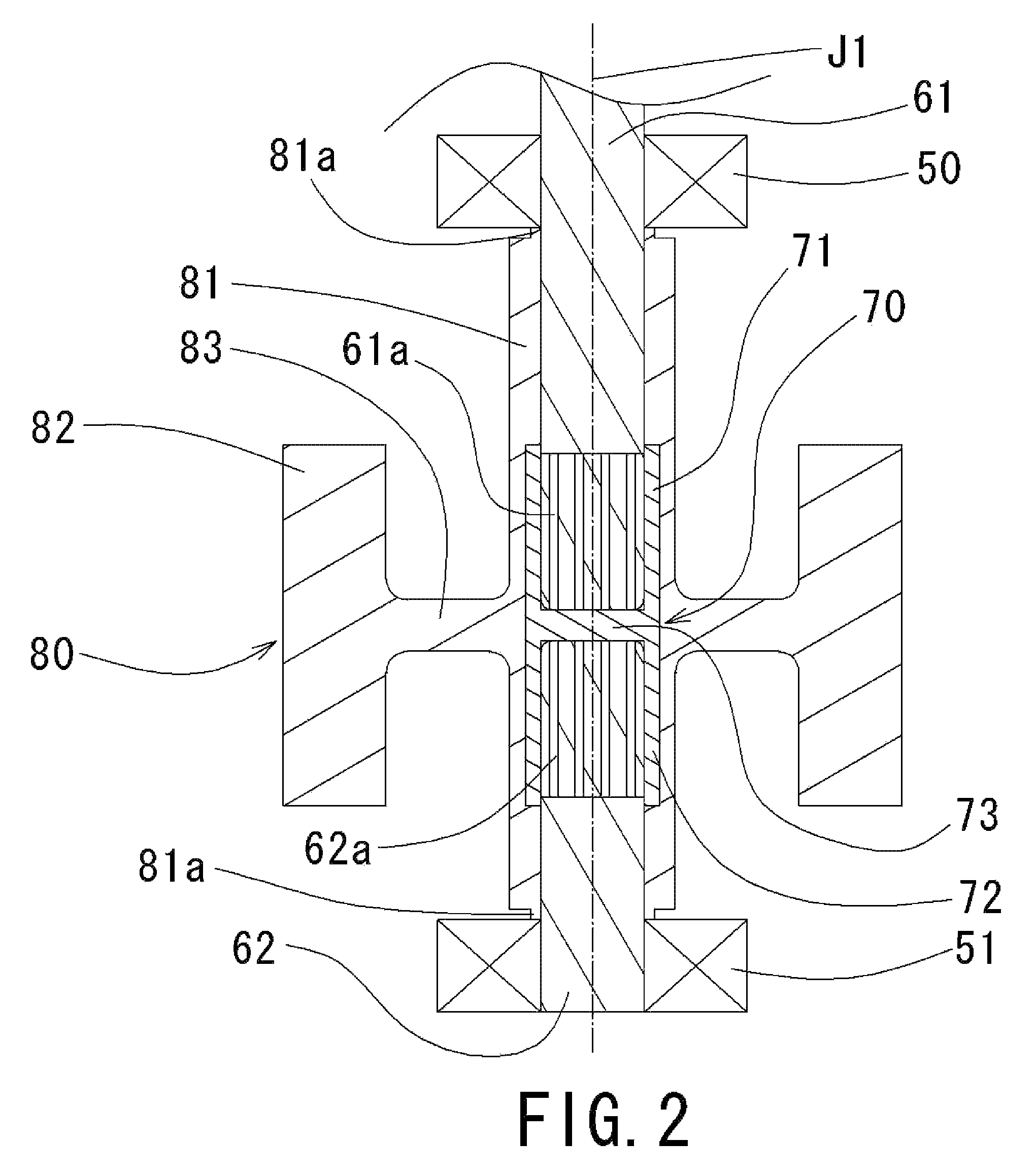
[0019]Referring to FIGS. 1 through 6, preferred embodiments of the present invention will be described in detail. It should be noted that in the explanation of preferred embodiments of the present invention, when positional relationships among and orientations of the different components are described as being up / down or left / right, ultimately positional relationships and orientations that are in the drawings are indicated; positional relationships among and orientations of the components once having been assembled into an actual device are not indicated. Meanwhile, in the following description, an axial direction indicates a direction parallel to a rotation axis, and a radial direction indicates a direction perpendicular to the rotation axis.

Structure of Motor of an Exemplary Preferred Embodiment

[0020]A motor according to an exemplary preferred embodiment of the present invention is now described referring to FIG. 1. FIG. 1 is a cross-sectional view of the motor when the motor is c...


PUM

PropertyMeasurementUnit
voltageaaaaaaaaaa
electrically insulatingaaaaaaaaaa
inner diameteraaaaaaaaaa

Abstract

A motor includes a shaft including upper and lower shaft members spaced axially away from each other. A shaft connecting member made of electrically insulating material is arranged axially between the upper and lower shaft members. The shaft connecting member is provided with fitting portions to which the upper and lower shaft members are to be fitted. While the upper and lower shaft members are secured to the shaft connecting member, the rotor magnet is integrally formed with the upper and lower shaft members and the shaft connecting member. With this configuration, an axial electric current is prevented from flowing through the shaft by the shaft connecting member.

Description

BACKGROUND OF THE INVENTION[0001]1. Field of the Invention[0002]The present invention relates to a motor. More particularly, the present invention relates to a structure for preventing electrochemical corrosion of a bearing in a motor.[0003]2. Description of the Related Art[0004]In motors driven by a higher voltage of 100 volts or higher and controlled by PWM (pulse width modulation) control, an axial electric current caused by a potential difference in the motor has been a problem for some time. The potential difference is produced by an unbalanced voltage applied to the motor, unevenness of a gap between a stator and a magnet, or a voltage change at a neutral point in PWM control, for example. That axial electric current causes an electric discharge in a bearing in which an electrically insulating layer exists, e.g., a roller bearing in which each of inner and outer rings is provided with an electrically insulating layer. The electric discharge roughens a bearing surface, especial...

Claims


Application Information

Patent Timeline
Patent Type & Authority Patents(United States)
IPC IPC(8): H02K37/12
CPCH02K7/003H02K5/1732Y10T29/49009H02K1/27H02K1/06
Inventor OKADA, TAKESHIMAENO, AKITOSHI
Owner NIDEC SHIBAURA CORP
Why Eureka
Try Eureka