Cooling structure of superconducting motor

a superconducting motor and cooling structure technology, applied in the direction of cooling/ventilation arrangement, magnetic circuit rotating parts, shape/form/construction, etc., can solve the problem of difficult formation of long hollow portions through a long rotating shaft, inefficient cooling of difficulty in sufficiently cooling the superconducting coil in such a case. problem, to achieve the effect of enhancing the cooling effect and easy formation of the cooling structur

Inactive Publication Date: 2010-02-23
SUMITOMO ELECTRIC IND LTD
View PDF10 Cites 7 Cited by
  • Summary
  • Abstract
  • Description
  • Claims
  • Application Information

AI Technical Summary

Benefits of technology

[0040]As described above, according to the present invention, the cooling structure for cooling the superconducting coil attached to the rotor is provided by forming the groove on the outer surface of the rotating shaft and disposing the refrigerant circulation tube inside the groove, instead of forming a hollow portion at the center of the rotating shaft. Thus, the cooling structure can easily be formed, as compared with the case where the hollow portion is provided in the rotating shaft.
[0041]Also, the refrigerant circulation tube is exposed to the outer surface of the rotating shaft. Thus, the refrigerant can be circulated at a position closer to the superconducting coil attached to the rotor than the case where a refrigerant circulation is provided on the center line of the rotating shaft. Consequently, cooling effect can be enhanced.

Problems solved by technology

Particularly, when cooling a superconducting coil attached to a rotor disposed at a center of a motor, it is inefficient to cool it from outside the motor.
Therefore, it is difficult to sufficiently cool the superconducting coil in such a case.
Particularly, in a case of a large motor, such as a series-coupled synchronous type motor used to drive a ship, it is difficult to form a long hollow portion through a long rotating shaft.

Method used


Image

  • Cooling structure of superconducting motor
  • Cooling structure of superconducting motor
  • Cooling structure of superconducting motor

Examples


first embodiment

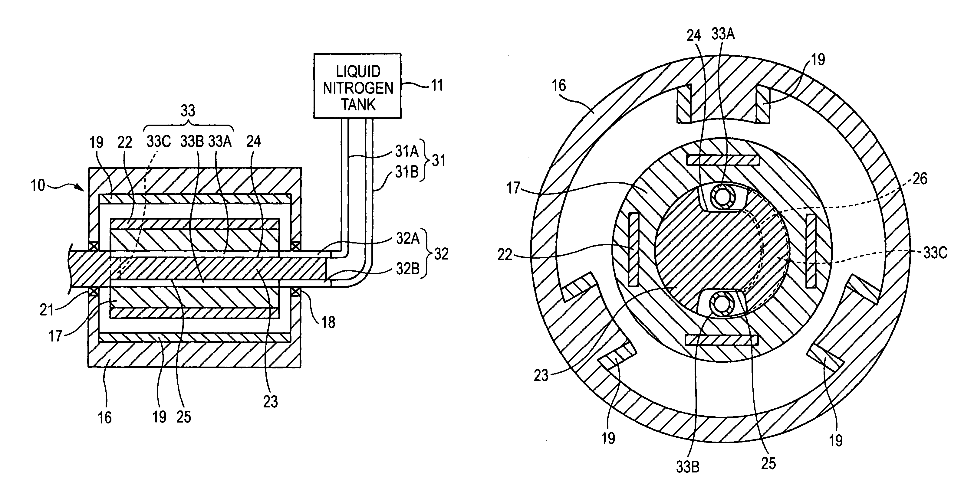
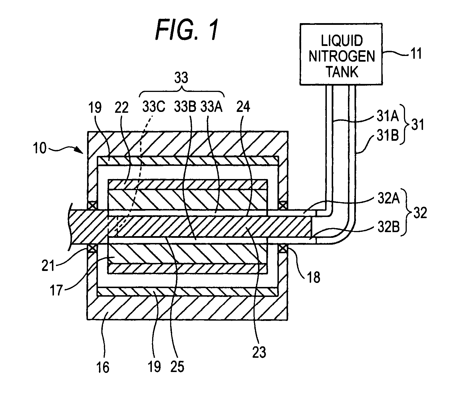
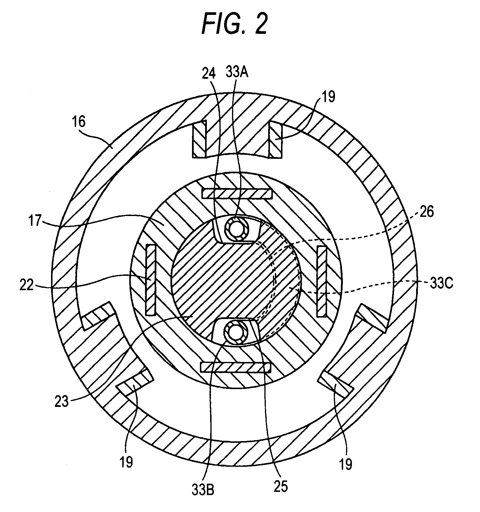
[0072]FIGS. 1 to 4 show the invention. A superconducting motor 10 may be used as a propulsion motor of a ship.

[0073]As shown in FIGS. 1 and 2, the superconducting motor 10 includes a stator 16 and a rotor 17 which is rotatably disposed inside a hollow portion of the stator 16, and it is a radial type in which a direction of a magnetic flux of a superconducting coil 22 attached to the rotor 17 is directed in a radial direction.

[0074]The rotor 17 is formed in a cylindrical shape, and may be made of a powder magnetic material. A rotating shaft 23 penetrates through a center of the rotor 17 and is fixed thereto. The rotating shaft 23 extends towards the exterior of the stator 16 through bearings 18 and 21.

[0075]The superconducting coil 22 (or field coil) made of a superconducting material is fixed to the rotor 17. As the superconducting material, bismuth-based or yttrium-based high temperature superconducting materials may be suitably used.

[0076]On the other hand, the stator 16 may be f...

second embodiment

[0092]FIGS. 6 and 7 show the invention.

[0093]The difference from the first embodiment is that the second embodiment is a motor of an axial type in which the stators are placed opposite to each other in the axial direction of the rotor, whereby a direction of a magnetic flux of the superconducting coil is directed in the axial direction.

[0094]In a superconducting motor 50 according to this embodiment, a pair of stators 53 and 54 is arranged so as to face each other on respective sides a rotor 52 fixed to a rotating shaft 51 with a predetermined gap being provided the respective sides of the rotor 52.

[0095]The rotor 52 is formed with a through hole 52a at a shaft center portion thereof, and the rotating shaft 51 is inserted through and fixed to the through hole 52a, whereby the rotor 52 and the rotating shaft 51 are corotated.

[0096]Magnetic field element mounting holes 52b are formed on the rotor 52 at intervals in a circumferential direction around the axis thereof. Superconducting c...


PUM


Abstract

In a cooling structure of a superconducting motor in which a superconducting coil is attached to a rotor, grooves are concavely provided on an outer surface of a rotating shaft that penetrates and is fixed to the rotor. A refrigerant is circulated through a refrigerant circulation pipe disposed inside the grooves to that the superconducting coil is cooled by the refrigerant.

Description

[0001]This is a U.S. National Stage application of PCT / JP2005 / 023125, filed Dec. 16, 2005, which claims priority to Japanese application 2004-374707, filed Dec. 24, 2004, the disclosures of which are both incorporated herein in their entirety by reference.TECHNICAL FIELD[0002]The present invention relates to a cooling structure of a superconducting motor. More specifically, the present invention relates to a structure for efficiently cooling a superconducting coil attached to a rotor of a drive motor mounted on ships, such as a government ship and a passenger ship.BACKGROUND ART[0003]In recent years, the development of a ship driven by electrically driving a motor has been advanced in view of suppressing a depletion of fuel resources, such as a gasoline, and an environmental deterioration due to exhaust gas. Specifically, a superconducting motor disclosed in JP-A-6-006907 (Patent Document 1) may be employed, thereby eliminating copper loss in a superconducting coil and achieving hig...

Claims


Application Information

Patent Timeline
Patent Type & Authority Patents(United States)
IPC IPC(8): H02K55/04H02K3/24H02K9/10H02K9/00
CPCH02K3/24H02K55/04H02K9/20Y02E40/625Y02E40/60H02K9/19
Inventor OKAZAKI, TORUOHASHI, SHINGOSUGIMOTO, HIDEHIKOTAKEDA, TOSHIO
Owner SUMITOMO ELECTRIC IND LTD
Why Eureka
Try Eureka