Broad band energy harvesting system and related methods

a technology of energy harvesting system and broad band, applied in piezoelectric/electrostrictive/magnetostrictive devices, piezoelectric/electrostriction/magnetostriction machines, electrical equipment, etc., can solve the problems of large repair cost and down time, material degradation of components, and increased weight and complexity of components being monitored, etc. , to achieve the effect of low quality factor, wide bandwidth and low quality factor

Active Publication Date: 2010-02-23
LOCKHEED MARTIN CORP
View PDF10 Cites 33 Cited by
  • Summary
  • Abstract
  • Description
  • Claims
  • Application Information

AI Technical Summary

Benefits of technology

[0014]In view of the foregoing, embodiments of the present invention advantageously provide a broad band energy harvesting system that reduces dependence on batteries or any other external power source. Embodiments of the present invention advantageously provide an energy harvesting system capable of generating or harvesting energy from a structure having environmental energy distributed over a wide frequency band. Embodiments of the present invention advantageously can also provide a single energy harvesting apparatus capable of working over a very broad range of frequencies, groups of which would be available in different locations on a structure. Embodiments of the present invention advantageously can additionally provide an energy harvesting apparatus capable of providing energy harvesting over multiple frequencies, simultaneously, within the wide frequency band.
[0016]Advantageously, the low quality factor and wide bandwidth allow each respective generator of the energy harvesting apparatus, in response to environmental energy emanating from the structure, to harvest a predefined minimum amount of energy from or at each of a plurality of discrete vibration frequencies adjacent the resonant frequency defining or otherwise falling within the bandwidth. That is, if energy or power is available from the structure at an associated minimum energy at one or more discrete vibration frequencies falling within the bandwidth of the respective generator, the energy harvesting apparatus can generate sufficient electric power to power an associated power consuming device such as, for example, a health monitoring sensor node. In order to configure each generator to have a low quality factor, each generator can include or interface with a damper or other resistive means positioned to dampen or otherwise reduce the magnitude of the isolations of the respective generator.
[0017]Further advantageously, each of the plurality of energy harvesting generators of each energy harvesting apparatus collectively provide energy harvesting over the plurality of modes to thereby provide energy harvesting over a substantial portion of the broad frequency range. That is, according to an embodiment of the present invention, a maximum frequency for a first generator bandwidth of a first one of the plurality of generators can overlap a minimum frequency for a second generator bandwidth of a second one of the plurality of generators, and so on, to thereby provide energy harvesting capability at the predefined minimum amount of energy over a substantial portion of the frequency range.
[0018]According to an embodiment of the present invention, the energy harvesting apparatus includes a plurality of cantilevered beams each carrying a piezoelectric material to form a respective one of the plurality of generators. Each cantilevered beam is preferably fixedly connected to a common backbone. The common backbone includes a resilient material configured to allow the transfer of energy between adjacent generators to thereby enhance energy harvesting.
[0019]Embodiments of the present invention can also include methods of harvesting energy from a structure. For example, according to an embodiment of the present invention, a method of harvesting energy from a structure can include providing an energy harvesting apparatus including a plurality of energy harvesting generators each connected to a non-fixed portion of a resilient common backbone and each adapted to oscillate at separate and distinct modes responsive to multifrequency environmental energy received from the structure. Also, in order to further enhance energy harvesting or increase in the number of discrete frequencies potentially providing a minimum amount of energy or power / power density needed by an associated power consuming device, the method can include the steps of damping the oscillations of at least one but preferably each of the generators to simultaneously reduce the quality factor and widen the bandwidth of the generator to thereby provide energy harvesting capability at a predefined minimum amount of energy over a substantial portion of a relatively broad frequency range.
[0020]According to an embodiment of the present convention, the method can also include the step of selecting separate and distinct modes for each of the generators to collectively maximize the number of discrete frequencies within the broad frequency range capable of providing a predefined minimum energy. That is, the modes can be selected to increase the number of discrete vibration frequencies to enhance receiving energy or power that, when harvested, is sufficient to meet the needs of the associated power consuming device. Further, the method can also include the step of carrying part of the energy from one of the generators to an adjacent generator through the resilient backbone to thereby increase total energy harvested by each of the plurality of generators.

Problems solved by technology

Various types of platforms such as, for example, aircraft structural components, aircraft skins, or other related components, when in operation are subjected to various environmental conditions such as stress and strain, exposure to temperature extremes, and significant vibration energy.
Due to the various environmental conditions such components can suffer material degradation over time.
Such wiring can, in some instances, undesirably result in increased weight and complexity of the component being monitored and / or the associated structure or component and are subject to damage or breakage requiring extensive repair costs and down time.
Depending upon available space, batteries can be inappropriate due to their size.
Batteries can also have a limited service life and therefore, typically require periodic inspection and / or replacement, are often positioned in locations difficult to reach, and often require costly disassembly and reassembly of the sensor or component to perform service on the battery.
Further, batteries may not be suitable due to environmental constraints, i.e., temperature changes often affect battery performance.
This type of sensor can typically consume very low amounts of power in the microwatt range.
Because power harvesting relies on energy being available in the vicinity of the energy harvesting device, the sensors positioned in the areas of environmental energy having a frequency different than the expected frequency often do not receive sufficient power to provide continuous sensing capability necessary to perform even sampled sensing using a small duty cycle.
Also, the available energy distribution may change such that an area of the structure once having a high level of environmental energy at an expected frequency or frequencies is now subject only to a low-level of such energy at such frequency or frequencies, making power availability less reliable.
Further, an operator installing the energy harvesting device may not know anything more than a range of potential frequencies that the energy harvesting device will have access to until immediately prior to actually installing the device in or on the vibrating structure, i.e., selecting the location on the structure to position the energy harvesting device.
Recognized by the Applicants is that energy harvesting devices having one or more discrete resonant frequencies configured to have a relatively high quality factor, and thus, a correspondingly relatively low bandwidth, may be unreliable in the expected frequency or frequencies of the environmentally generated vibration energy of the structure if the expected frequency or frequencies of the vibration energy do not fairly precisely match the actual frequency or frequencies of the environmentally generated vibration energy.

Method used


Image

  • Broad band energy harvesting system and related methods
  • Broad band energy harvesting system and related methods
  • Broad band energy harvesting system and related methods

Examples


Embodiment Construction

[0033]The present invention will now be described more fully hereinafter with reference to the accompanying drawings, which illustrate embodiments of the invention. This invention may, however, be embodied in many different forms and should not be construed as limited to the illustrated embodiments set forth herein. Rather, these embodiments are provided so that this disclosure will be thorough and complete, and will fully convey the scope of the invention to those skilled in the art. Like numbers refer to like elements throughout. Prime notation, if used, indicates similar elements in alternative embodiments.

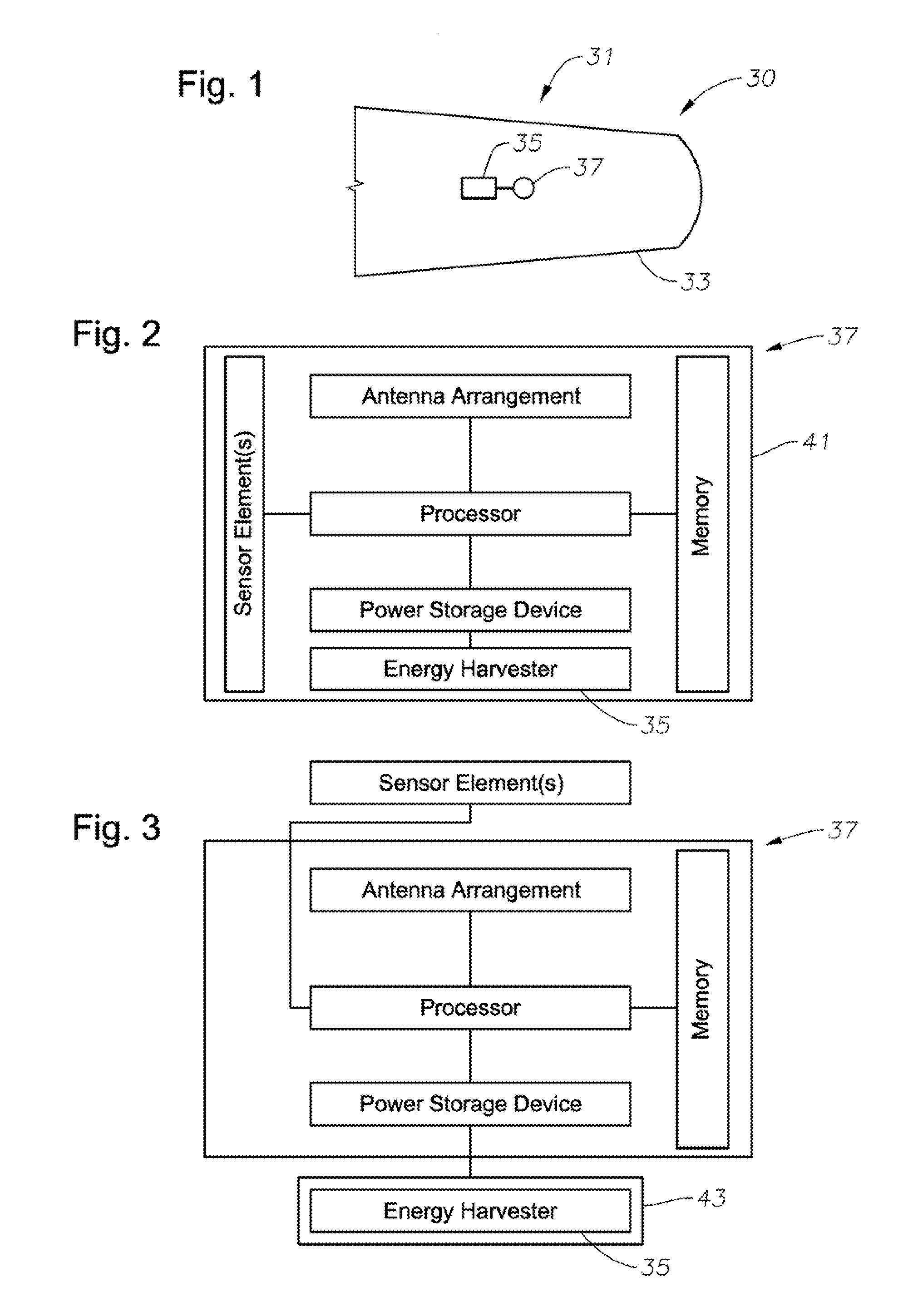
[0034]The various systems such as, for example, multi-node health monitoring sensor systems require power to perform their associated function. In wireless structural health monitoring applications, for example, where batteries are not appropriate due to their size, longevity, or environmental constraints, or when it is desired to supplement batteries with alternate energy sour...


PUM


Abstract

A broad band energy harvesting system to harvest energy from a structure and associated methods are provided. The system includes a structure carrying a plurality of environmentally produced vibration frequencies extending over a frequency range and an energy harvesting apparatus positioned in vibration receiving communication with the structure to harvest energy from the structure. Each energy harvesting apparatus includes broadly tuned energy harvesting generators having relatively low quality factor and corresponding relatively wide bandwidth. The energy harvesting generators collectively provide energy harvesting over multiple modes to thereby provide energy harvesting over a substantial portion of the frequency range. Each energy harvesting generator can include a cantilevered beam connected to a common backbone comprised of a resilient material configured to transfer energy between adjacent generators to further enhance energy harvesting.

Description

BACKGROUND OF THE INVENTION[0001]1. Field of the Invention[0002]The present invention relates generally to energy harvesting systems. More specifically, the present invention relates to a broad band energy harvesting system and related methods to harvest energy from the structure.[0003]2. Description of the Related Art[0004]Various types of platforms such as, for example, aircraft structural components, aircraft skins, or other related components, when in operation are subjected to various environmental conditions such as stress and strain, exposure to temperature extremes, and significant vibration energy. Due to the various environmental conditions such components can suffer material degradation over time.[0005]Structural health monitoring helps promote realization of the full potential of such components. Remotely positioned sensors and / or nodes have been installed adjacent to such structures / components to monitor various parameters such as, for example, strain levels, stress, te...

Claims


Application Information

Patent Timeline
Patent Type & Authority Patents(United States)
IPC IPC(8): H01L41/08H01L41/083
CPCH01L41/1136H02N2/188H10N30/306
Inventor BERKCAN, ERTUGRULWOJNAROWSKI, ROBERT JOHNANDARAWIS, EMAD ANDARAWISRAO, SAMANTHADELGADO, ELADIO
Owner LOCKHEED MARTIN CORP
Why Eureka
Try Eureka