
Fast rendering of pyramid lens distorted raster images

Inactive Publication Date: 2010-02-23
INTELLECTUAL VENTURES ASSETS 186 LLC
View PDF275 Cites 61 Cited by
  • Summary
  • Abstract
  • Description
  • Claims
  • Application Information

AI Technical Summary

Benefits of technology

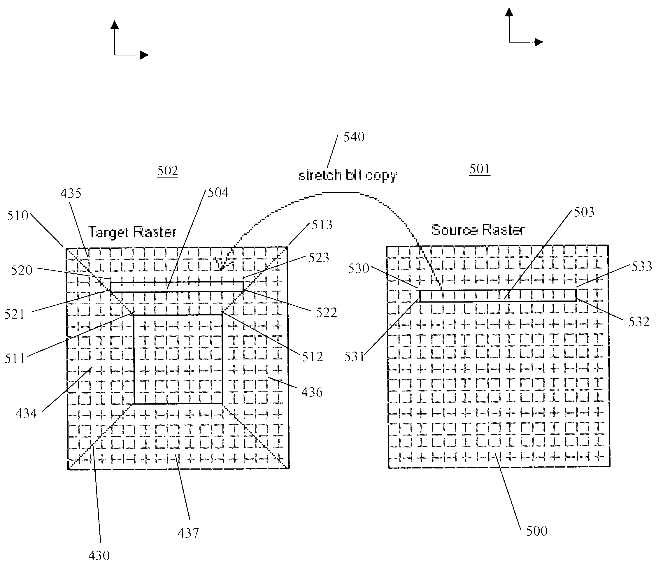
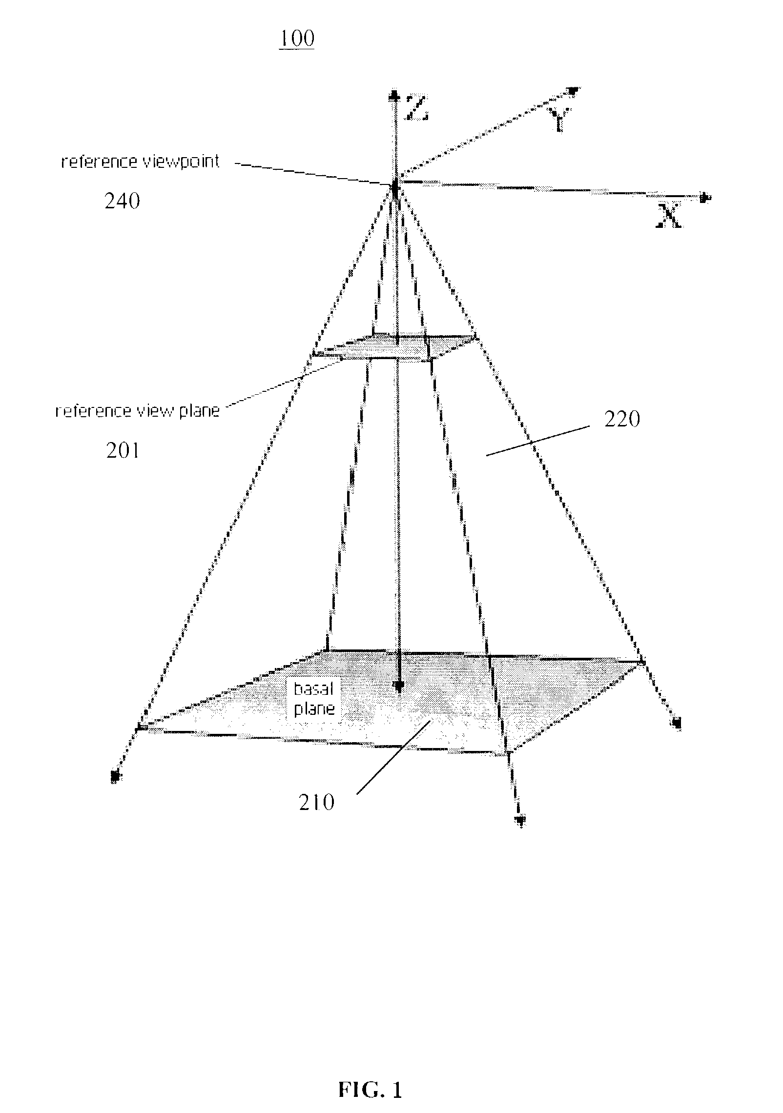
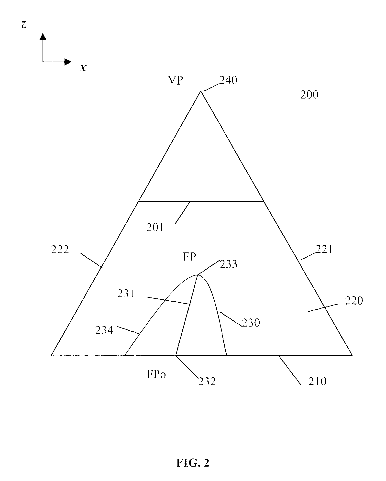
[0011]In general, the present invention provides for the effective presentation of pyramid lens type presentations in detail-in-context presentation systems through the use of improved rendering techniques.
[0017]Advantageously, the pyramid lens rendering method of the present invention may be applied to a wide variety of detail-in-context presentations where fast rendering is required and where hardware based accelerating devices are not available. In addition, the present invention does not require time consuming rasterizing of polygonal surfaces.

Problems solved by technology

Display screens are limited in size, thus presenting a challenge to graphical user interface design, particularly when large amounts of information are to be displayed.
While these solutions are suitable for a large number of visual display applications, these solutions become less effective where sections of the visual information are spatially related, such as maps, three-dimensional representations, newspapers and such like.
In this type of information display, panning, zooming and / or scrolling is not as effective as much of the context of the panned, zoomed or scrolled display is hidden.
One shortcoming of these detail-in-context presentation systems is that the rendering of a raster image which has undergone a distortion through the application of one or more lenses (e.g. pyramid lenses) can be time consuming.
This technique can provide fast results, especially when combined with the use of accelerated three-dimensional rendering hardware, but rendering can be slow when no such hardware is present.

Method used


Image

  • Fast rendering of pyramid lens distorted raster images
  • Fast rendering of pyramid lens distorted raster images
  • Fast rendering of pyramid lens distorted raster images

Examples


Embodiment Construction

[0027]In the following description, numerous specific details are set forth to provide a thorough understanding of the invention. However, it is understood that the invention may be practiced without these specific details. In other instances, well-known software, circuits, structures and techniques have not been described or shown in detail in order not to obscure the invention. In the drawings, like numerals refer to like structures or processes.

[0028]The term “data processing system” is used herein to refer to any machine for processing data, including the computer systems and network arrangements described herein. The term “Elastic Presentation Space” (“EPS”)(or “Pliable Display Technology” (“PDT”)) is used herein to refer to techniques that allow for the adjustment of a visual presentation without interfering with the information content of the representation. The adjective “elastic” is included in the term as it implies the capability of stretching and deformation and subseque...


PUM


Abstract

A method for generating a presentation of a region-of-interest in an information representation including the steps of: selecting a viewpoint for the region-of-interest; creating a lens surface for the region-of-interest; the lens surface having a focal region and a shoulder region surrounding the focal region; creating a transformed presentation by: determining boundaries in the representation for the focal region and the shoulder region; determining boundaries on the lens surface corresponding to the boundaries in the representation by applying a distortion function defining the lens surface to the boundaries in the representation; perspectively projecting the boundaries on the lens surface onto a plane spaced from the viewpoint; and, copying information in the representation lying within the boundaries in the representation onto the focal region and the shoulder region of the lens surface using respective focal region and shoulder region stretch bit-block transfer operations; and, displaying the transformed presentation on a display screen to generate the presentation of the region-of-interest.

Description

[0001]This application claims priority from Canadian Patent Application No. 2,370,752 filed Feb. 5, 2002, the disclosure of which is incorporated herein by reference.[0002]The invention relates to the field of computer graphics processing and more specifically to a method and system for the fast rendering of pyramid lens distorted raster images in detail-in-context presentations.BACKGROUND OF THE INVENTION[0003]Display screens are the primary interface for displaying information from a computer. Display screens are limited in size, thus presenting a challenge to graphical user interface design, particularly when large amounts of information are to be displayed. This problem is normally referred to as the “screen real estate problem”.[0004]Well-known solutions to this problem include panning, zooming, scrolling or combinations thereof. While these solutions are suitable for a large number of visual display applications, these solutions become less effective where sections of the visu...

Claims


Application Information

Patent Timeline
IPC IPC(8): G06T15/10G09G5/00G06T15/00
CPCG06T3/0018G06T3/047
Inventor KOMAR, ROBERTSHOEMAKER, GARTH B. D.TIGGES, MARK
Owner INTELLECTUAL VENTURES ASSETS 186 LLC
Learn More