
Biomagnetic measurement apparatus

a technology of biomagnetic measurement and apparatus, which is applied in the field of biomagnetic measurement apparatus, can solve the problems of conventional problems, observation of cams, and difficulty in visualizing the electrical activity in the whole heart muscle of the subject,

Inactive Publication Date: 2010-02-23
HITACHI HIGH-TECH CORP
View PDF22 Cites 3 Cited by
  • Summary
  • Abstract
  • Description
  • Claims
  • Application Information

AI Technical Summary

Benefits of technology

Enables the observation of electrical activity in the whole heart by displaying current distribution diagrams on a planispheric chart, facilitating the visualization of electrical excitement across both sides of the heart.

Problems solved by technology

Consequently, it has been impossible to observe the CAMs obtained from both of the measurement surfaces at a time, thereby it has been difficult to visually grasp the electrical activity in the whole heart muscles of the subject.
This has been a conventional problem.

Method used


Image

  • Biomagnetic measurement apparatus
  • Biomagnetic measurement apparatus
  • Biomagnetic measurement apparatus

Examples


second embodiment

[0231]Hereunder, another (the second) embodiment of the present invention will be described with reference to the accompanying drawings.

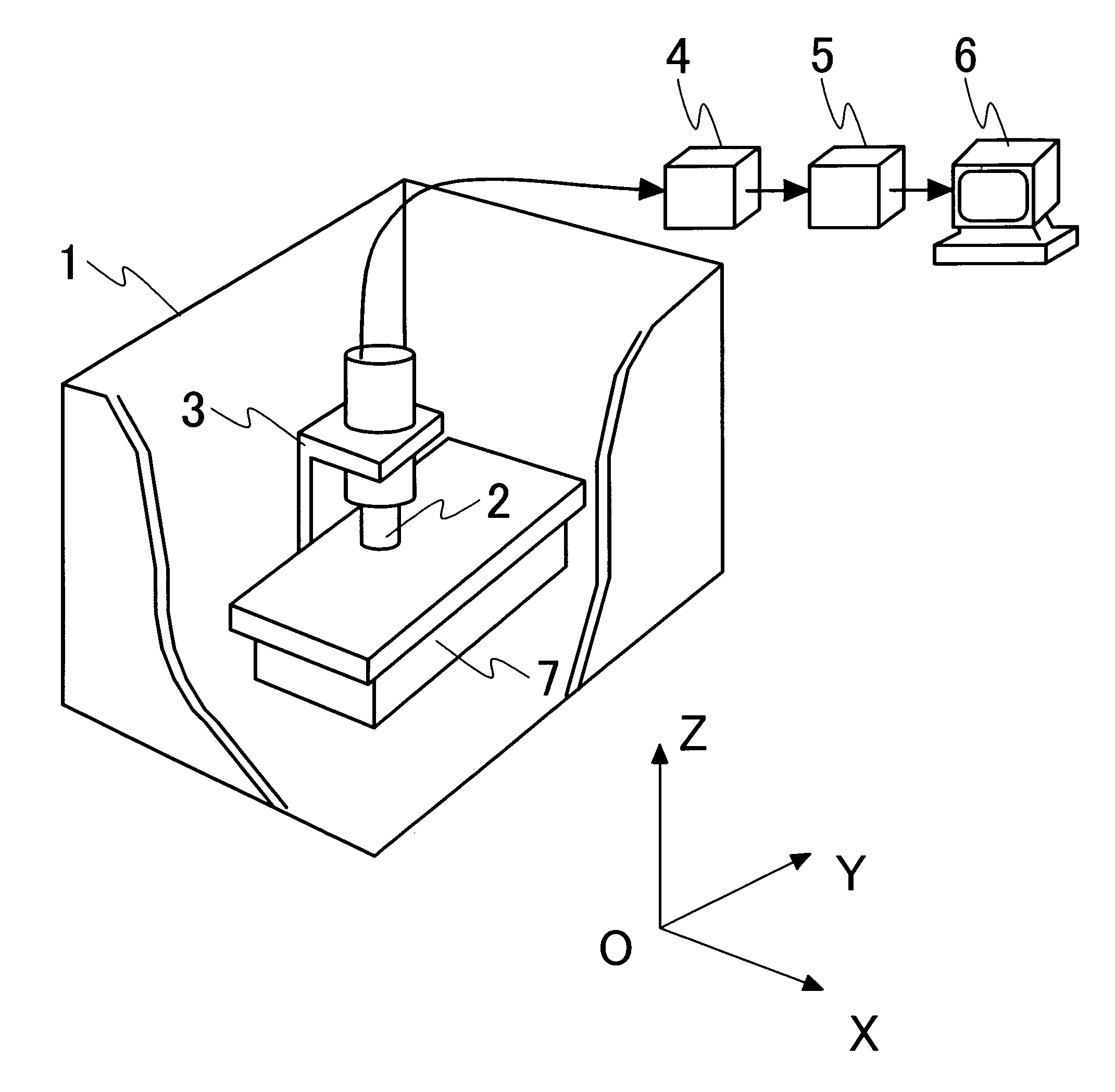
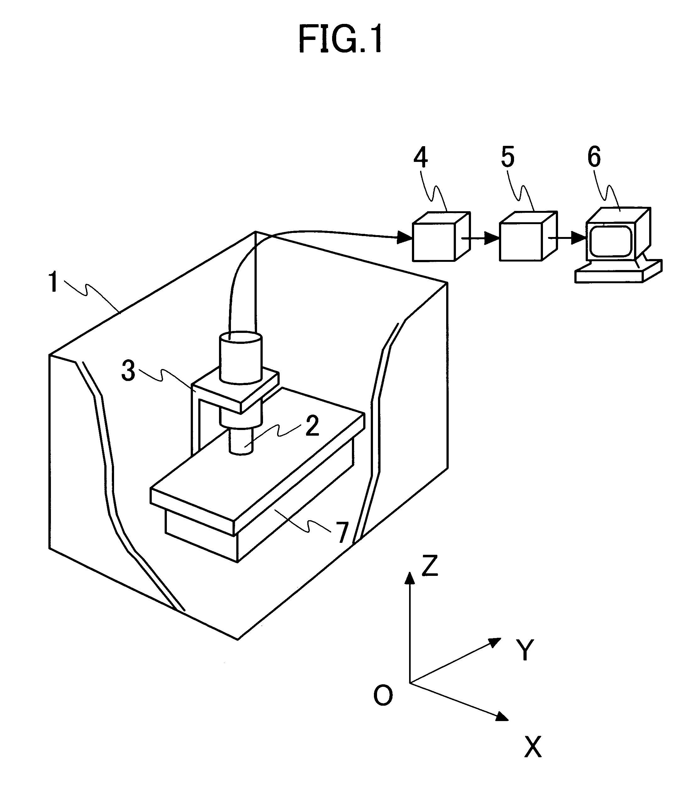
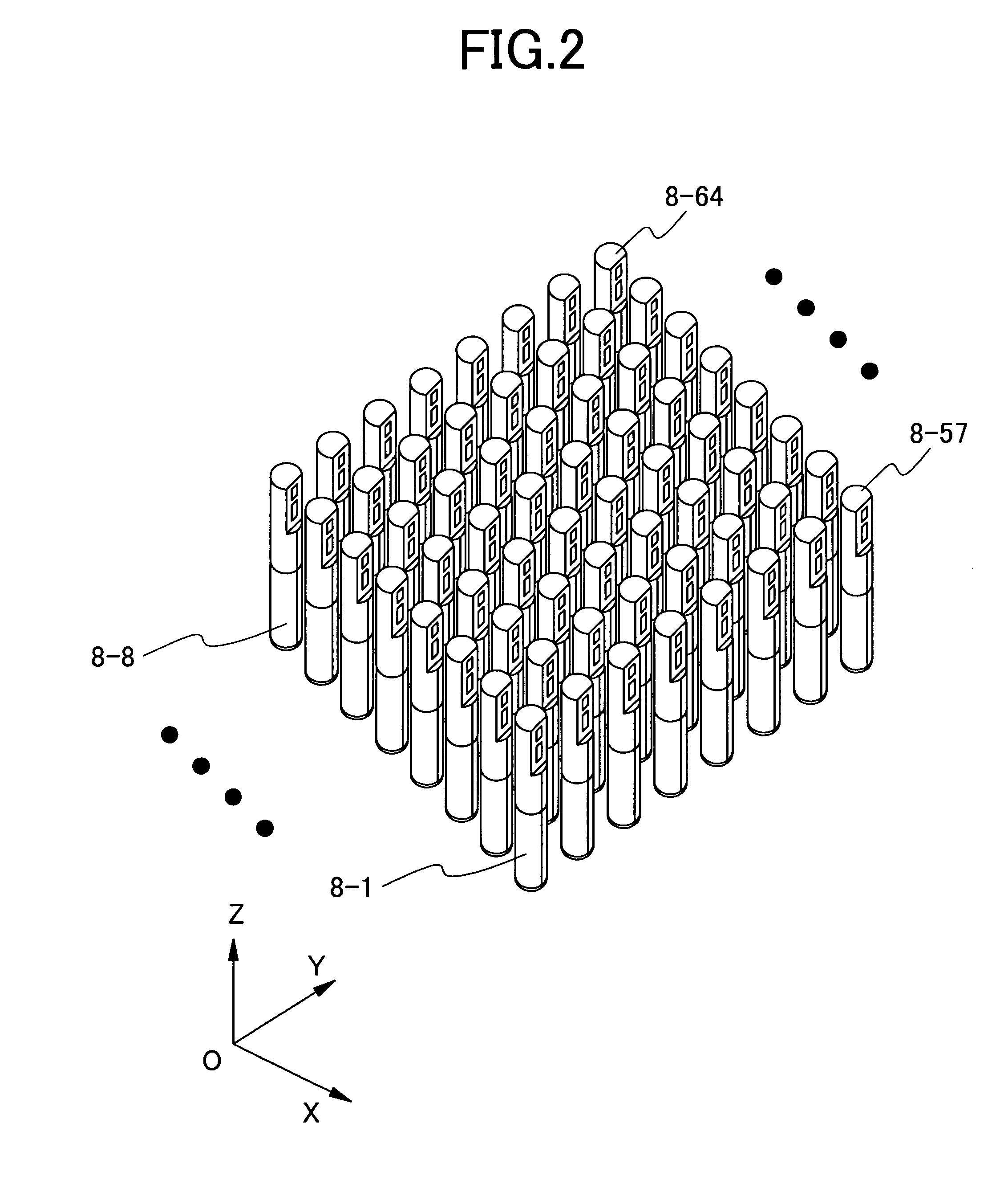
[0232]1. According to the first aspect of the present invention, the biomagnetic measurement apparatus comprises a plurality of magnetic field sensors disposed two-dimensionally to detect a magnetic field from a subject respectively, an arithmetic processing unit for collecting the magnetic fields to be measured from the first and second directions of the subject as first and second magnetic field data to process their data arithmetically, and a display device for displaying a result of the arithmetic processing.

[0233]The first direction is a direction from the thoracic (front) side of the subject and the second direction is a direction from the back side of the subject.

[0234]The arithmetic processing is executed to convert each of the positions of the plurality of magnetic field sensors to polar coordinates represented by a radius vector r and an o...


PUM


Abstract

A CAM (current arrow map) 71 and another CAM 72 are obtained from magnetocardiogram waveforms measured from both front and back sides of a subject using data at a point of time of an R-wave peak, then the coordinates of the CAM 72 are inverted in both x and y axis directions to obtain a CAM 73. The coordinates of each of the CAMs 71 and 73 are converted to polar coordinates to obtain CAMs 74 and 75 at both front and back sides of the subject. After that, the CAM 74 is adjusted to the CAM 76 in scale to obtain a CAM 76 , and CAMs 74 and 76 are combined. Then, the CAM data at measuring points on each measuring-points-missing radius vector is inserted through an arithmetic processing by interpolation so that CAM data at every measuring point on a planispheric chart 77 are connected to each another consecutively.

Description

CLAIM OF PRIORITY[0001]The present invention claims priority from Japanese application JP 2004-283010 filed on Sep. 29, 2004, the content of which is hereby incorporated by reference into this application.FIELD OF THE INVENTION[0002]The present invention relates to a biomagnetic measurement apparatus for measuring biomagnetic fields generated from living bodies with use of magnetometers.FIELD OF THE INVENTION[0003]In diagnoses of heart diseases such as arrhythmia, ischemic cardiac disease, etc., it is very important to visualize electro-physiological phenomena to occur in cardiac muscles. The biomagnetic measurement apparatus is one of such apparatuses for visualizing the electro-physiological phenomena. The biomagnetic measurement apparatus can measure very weak magnetocardiograms generated from respective hearts at multiple points in a noninvasive and non-contact manner and visualize the distribution of a current that flows in the cardiac muscles with use of measured magnetocardio...

Claims


Application Information

Patent Timeline
Patent Type & Authority Patents(United States)
IPC IPC(8): A61B5/00
CPCA61B5/04007A61B5/742A61B5/243
Inventor KANDORI, AKIHIKOMIYASHITA, TSUYOSHIOGATA, KUNIOMI
Owner HITACHI HIGH-TECH CORP
Learn More