Glass coating suspension deep undercooling fast directional solidification device and solidification method thereof

A directional solidification, glass-clad technology, applied in casting molding equipment, molds, cores, etc., can solve the problems of difficulty in obtaining fine columnar crystals, difficulty in excitation, etc., and achieve the effect of low production cost and simple and convenient operation.

Active Publication Date: 2017-06-30
ZHENGZHOU UNIV
View PDF8 Cites 2 Cited by
  • Summary
  • Abstract
  • Description
  • Claims
  • Application Information

AI Technical Summary

Problems solved by technology

[0004] The technical problem to be solved by the present invention is: in view of the defects that the existing deep supercooled rapid directional solidification technology is difficult to obtain fine columnar crystals and difficult to excite, the present invention provides a glass-coated suspension deep supercooled rapid directional solidification device and solidification method

Method used


Image

  • Glass coating suspension deep undercooling fast directional solidification device and solidification method thereof

Examples


Embodiment 1

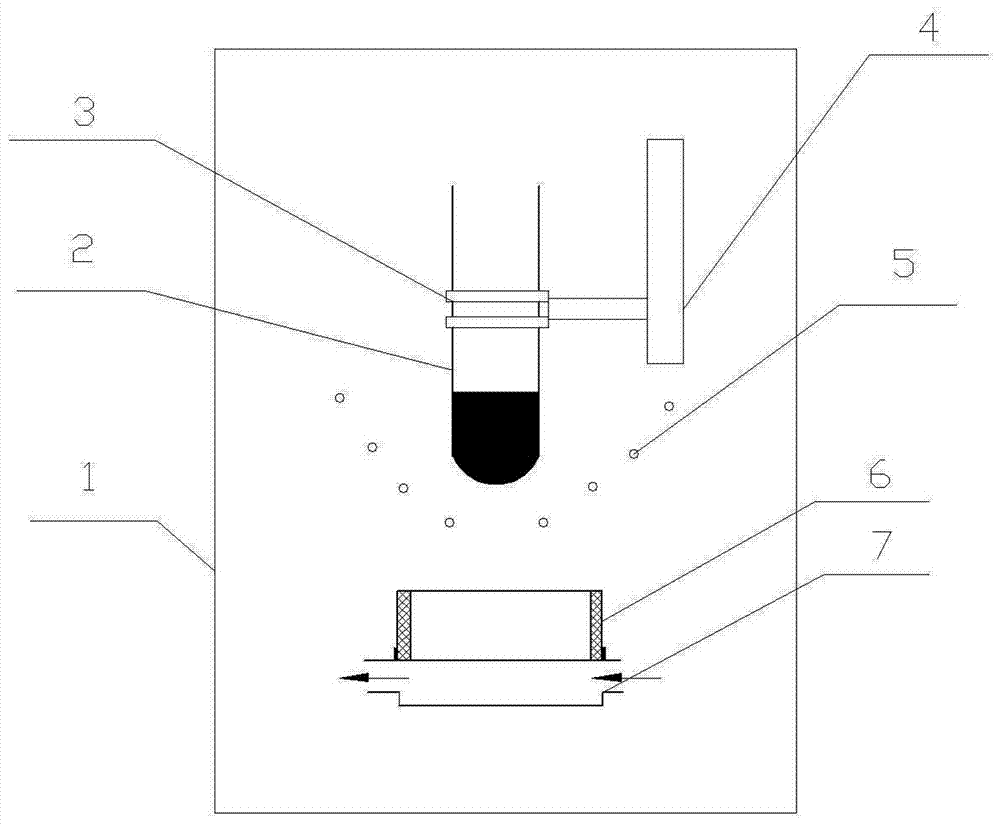
[0033] See attached figure 1 , The glass-coated suspension deep subcooling rapid directional solidification device of the present invention includes a closed furnace body (1), and a closed glass tube (2) with one end closed inside the closed furnace body (1), a glass tube holder (3), Ball screw (4), induction heater (5), heat insulation formwork (6) and water-cooled copper mold (7);

[0034] In the closed furnace body (1), there is a closed glass tube (2) above the induction heater (5). The glass tube (2) moves up and down controlled by the glass tube holder (3). The device (3) is driven by the ball screw (4); under the induction heater (5), there is a heat insulation formwork (6), and the lower part of the heat insulation formwork (6) is provided with a water-cooled copper mold (7); The heat insulation formwork (6) and the water-cooled copper mold (7) form a cavity.

Embodiment 2

[0035] Embodiment 2: basically the same as Embodiment 1, the difference is:

[0036] The glass tube (2) with one end closed is a high borosilicate glass tube, and the glass tube (2) is filled with alloy raw materials; the outer diameter of the high borosilicate glass tube (2) is 6mm, and the wall thickness is 0.5mm; the induction The heater (5) is made of copper tube and has a conical shape; the number of turns of the induction coil of the induction heater (5) is 3 turns, and the cone angle of the cone is 60°C; the water-cooled copper mold (7) is disc shape.

Embodiment 3

[0037] Embodiment 3: basically the same as Embodiment 1, the difference is:

[0038]The glass tube (2) with one end closed is a high borosilicate glass tube, and the glass tube (2) is filled with alloy raw materials; the outer diameter of the high borosilicate glass tube (2) is 20 mm, and the wall thickness is 3 mm; the induction heating The device (5) is made of copper tube and is conical; the number of turns of the induction coil of the induction heater (5) is 3 turns, and the cone angle of the cone is 60°C; the water-cooled copper mold (7) is disc-shaped shape.


PUM

PropertyMeasurementUnit
Outer diameteraaaaaaaaaa
Wall thicknessaaaaaaaaaa
Number of turnsaaaaaaaaaa

Abstract

The invention discloses a glass coating suspension deep undercooling fast directional solidification device and a solidification method thereof. The solidification device comprises a closed furnace body. A glass pipe, a glass pipe clamp, a ball screw, an induction heater, a thermal insulation mold shell and a water cooling copper mold are arranged in the closed furnace body. The glass pipe in the closed furnace body is placed on the clamp. The clamp is driven by the ball screw. The glass pipe is filled with alloy raw materials. The closed end of the glass pipe is located in the inner axial position of the heater. After installation, the closed furnace body is vacuumized and is filled with argon. A power source of the heater is started for heating, thus the alloy raw materials are subjected to suspension melting, an alloy melt is purified, heating is continued, and thus the alloy melt is overheated. The electric current of the heater is lowered, and a deep undercooling alloy melt is obtained. Under the action of the gravity, the deep undercooling alloy melt enters a mold cavity formed by the water cooling copper mold and the thermal insulation mold shell. Fast one-way growth of a block sample is achieved. In the operation process of the solidification method, expensive Ga-In-Sn liquid alloy is not used, thus production cost is low, and operation is simple and convenient.

Description

technical field [0001] The invention relates to a deep supercooled directional solidification technology, which belongs to the technical field of metal material preparation and processing. In particular, it relates to a glass-coated suspension deep supercooled rapid directional solidification device and a solidification method. Background technique [0002] The ultra-fine columnar grain structure combines the characteristics of fine grain and columnar grain, showing excellent mechanical properties. For example, low-alloy steel with ultra-fine columnar grains has tensile strength, elongation and room temperature impact toughness as high as 1.84 GPa, 15% and 226J respectively, and its toughness is 16 times higher than that of as-cast samples (Y. Kimura, T. Inoue , F. Yin, K. Tsuzaki. Inverse temperature dependence of toughness in an ultrafine grain-structure steel. Science, 2008, 320: 1057-1060). At present, the ultra-fine columnar grain structure is mainly obtained by rolli...

Claims


Application Information

Patent Timeline
IPC IPC(8): B22C9/06B22D27/04B22D1/00
CPCB22C9/06B22D1/00B22D27/045
Inventor 王成铎李松杰孙玉福张少军
Owner ZHENGZHOU UNIV
Why Eureka
Try Eureka