
Electrical connection box

a technology of electrical connection box and connection box, which is applied in the direction of electrical apparatus casing/cabinet/drawer details, coupling device connection, casing/cabinet/drawer details, etc., can solve the problems of short circuit between internal wiring and electric components, short circuit between wiring or electric components, water entering the electrical connection box,

Inactive Publication Date: 2010-03-02
YAZAKI CORP
View PDF16 Cites 35 Cited by
  • Summary
  • Abstract
  • Description
  • Claims
  • Application Information

AI Technical Summary

Benefits of technology

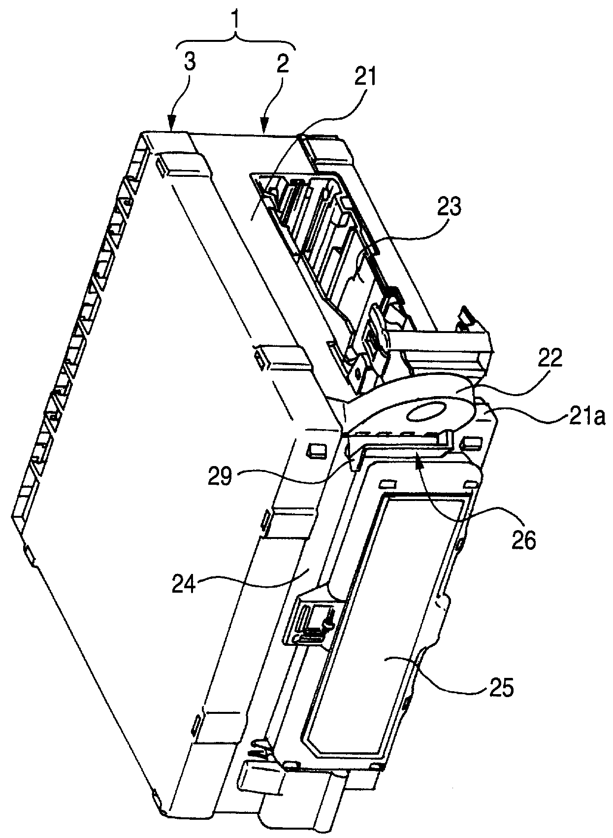
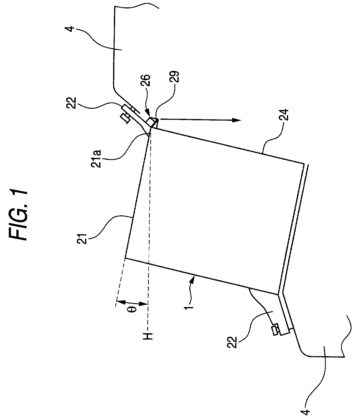
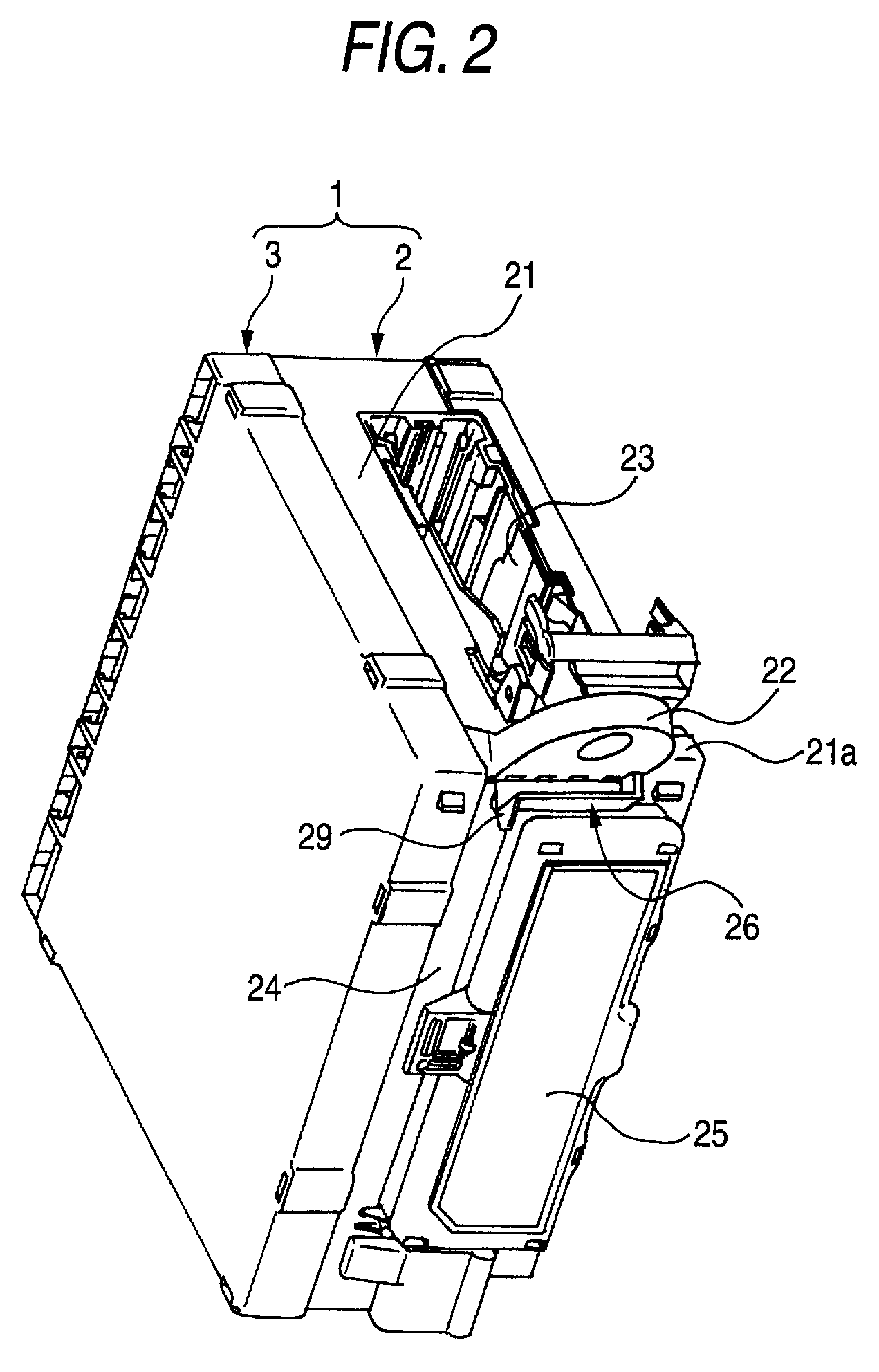
[0018]In the above configuration, water on the top wall surface of the electrical connection box inclined to a horizontal plane flows into the drainage channel provided along the lower-placed edge of the top wall surface. Then, the water is discharged from the drain port provided at one end of the drainage channel. Because this drain port is placed at a horizontally outer side than the side wall surface, which is connected to an edge of the top wall surface, in the electrical connection box, the water discharged from the drain port runs down without trickling the side wall surface of the electrical connection box. Consequently, water can be prevented from entering the inside of the electrical connection box. Accordingly, the internal wiring and electric components can be prevented from being short-circuited.
[0019]The side wall is perpendicular to the top wall, which is inclined to a horizontal plane, of the electrical connection box. Or the electrical connection box shaped like a rectangular parallelepiped is attached to a mount member by being tilted so that the top wall surface is inclined to a horizontal plane. Thus, the drain port is naturally placed at a horizontally outer side than the side wall surface of the electrical connection box. Accordingly, it is unnecessary to protrude the drain port largely from the side wall surface. The miniaturization of the electrical connection box can be achieved. Also, water can be prevented by a simple structure from entering the inside of the electrical connection box. Consequently, the internal wiring and electric components can be prevented from being short-circuited.
[0020]The invention can provide an electrical connection box, which can surely prevent wiring and electric components from being short-circuited.

Problems solved by technology

However, there is a fear that due to external factors, for example, vehicle vibrations and a negative pressure, water trickling along the side end portion of the wiring board 103 may run to the other part of the wiring board 103 until discharged completely, so that wiring or electric components may be short-circuited.
However, even in the case where a drainage structure is provided on the outer side of the electrical connection box, when water is made to trickle along a side wall surface of the electrical connection box to run down, there is a fear that during water trickles along the side wall surface of the electrical connection box, the water may enter the electrical connection box and short-circuit internal wiring and electric components, due to the external factors, or to a capillary phenomenon occurring between a body and a lid for covering the body, both of which generally constitute the electrical connection box.

Method used


Image

  • Electrical connection box
  • Electrical connection box
  • Electrical connection box

Examples


Embodiment Construction

[0027]Hereinafter, a preferred embodiment of the invention is described with reference to the accompanying drawings.

[0028]As shown in FIGS. 1 and 2, an entire electrical connection box 1 according to the present embodiment is shaped like a substantially rectangular parallelepiped. The electrical connection box 1 has a substantially rectangular parallelepiped box body 2 which is opened in one surface thereof, and a lid 3 which closes the opening of the box body 2.

[0029]The box body 2 is attached to mount members 4, for example, a vehicle frame, through brackets 22 so that the opening is directed horizontally, and that the top wall surface 21 is inclined to the horizontal plane H at a predetermined angle θ. The lid 3 is fit onto an edge portion of the opening of the box body 2 to thereby close the opening directed horizontally.

[0030]The brackets 22 are provided at diagonally opposing paired corner portions of the box body 2, respectively. One of the brackets 22 is provided at the lowe...


PUM


Abstract

An electrical connection box includes a box body. The box body has a top wall and a side wall. The top wall is inclined to a horizontal plane and has an edge portion arranged at a lower side in an inclination of the top wall. The side wall is connected to an edge portion of the top wall. A drainage channel is provided along the edge portion of the top wall. A drainage port is provided at an edge of the drainage channel. The drainage port is placed at a position spaced from the side wall.

Description

BACKGROUND OF THE INVENTION[0001]The present invention relates to an electrical connection box mounted in a vehicle, such as an automobile.[0002]Generally, electrical connection boxes have electric components, such as a wiring board, a fuse, a relay, and a connector. However, for example, an electrical connection box to be mounted in an automobile is sometimes installed in an engine room. Thus, such an electrical connection box takes a waterproof countermeasure to prevent electric components, such as a wiring board, from being short-circuited due to water caused by, e.g., an automobile wash to enter an engine room (see, e.g., JP-A-2002-152943).[0003]As illustrated in FIG. 5, JP-A-2002-152943 discloses an electric connection box 101. A wiring board 103, on which a fuse housing 102 is mounted, is mounted in the electrical connection box 101 so as to be substantially perpendicular to a surface thereof. The fuse housing 102 has drainage grooves 104a and 104b and a water-stop wall 105. A...

Claims


Application Information

Patent Timeline
Patent Type & Authority Patents(United States)
IPC IPC(8): H02G3/08
CPCH01R13/5227
Inventor KUBOTA, KATSUHIRO
Owner YAZAKI CORP
Learn More