
Mixer with feedback

a feedback and mixer technology, applied in the field of radio communication systems, can solve the problems of difficult implementation of rf selectivity, inability to easily implement rf selectivity, and difficult integration of radio receivers, so as to increase the compression point of a receiver and enhance the receiver gain

Inactive Publication Date: 2010-03-02
OPTIS WIRELESS TECH LLC
View PDF45 Cites 5 Cited by
  • Summary
  • Abstract
  • Description
  • Claims
  • Application Information

AI Technical Summary

Benefits of technology

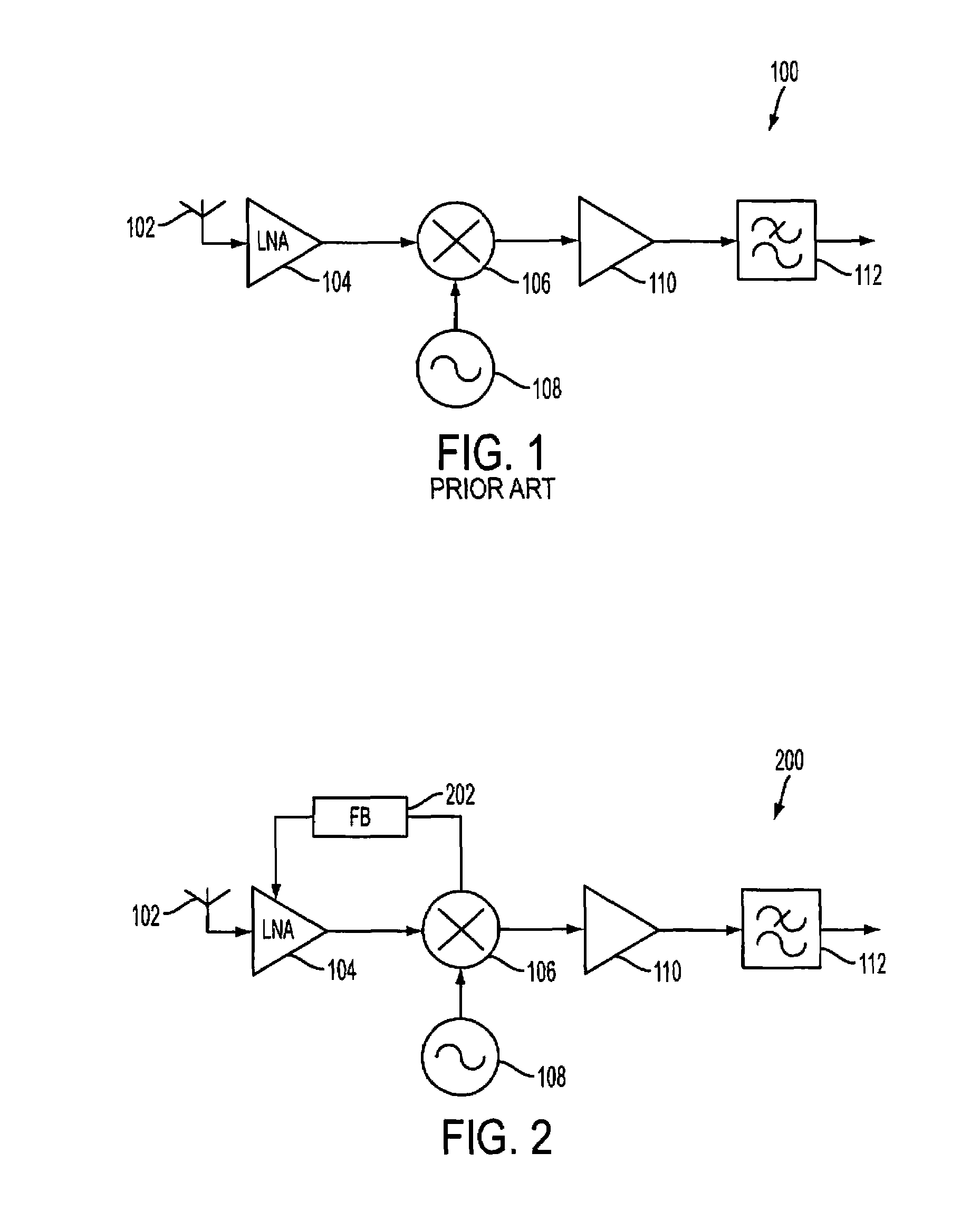
The present invention provides a method and system for improving the compression point of a receiver by using a feedback signal from a mixer. This feedback signal prevents the receiver from going into compression on strong out-of-band signals and enhances the receiver's gain at the desired frequency. This results in a tunable receiver that can selectively filter out signals over a wide range of frequencies. The invention also includes a radio frequency receiver with a mixer feedback network that provides a feedback signal to the low noise amplifier, which in turn controls the gain of the receiver. Overall, the invention improves the performance and flexibility of radio frequency receivers.

Problems solved by technology

A challenge in modern radio communication systems has been, and continues to be, to design receivers (and transmitters) that can meet increasingly strict performance standards while fitting into ever shrinking packages.
Integrated radio receivers, however, cannot easily implement RF selectivity due to the very high quality (Q) factors required in modern communication systems.
Band selectivity is also difficult to implement on a chip.
Adding filters, however, has the drawback of increasing the cost, size, and complexity of the receiver.
But desensitization and distortion usually become significant only when the power level at the low noise amplifier input approaches the receiver compression point.

Method used


Image

  • Mixer with feedback
  • Mixer with feedback
  • Mixer with feedback

Examples


Embodiment Construction

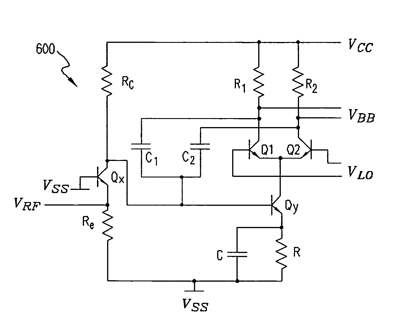
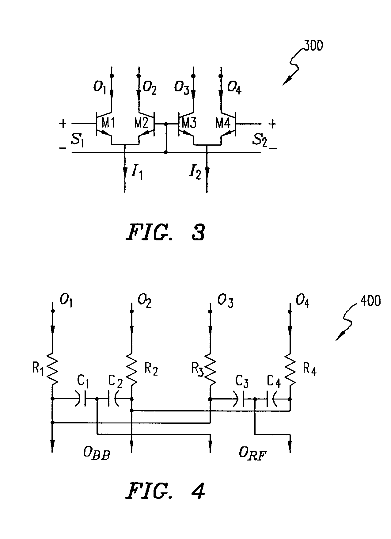
[0027]Following is a detailed description of the invention with reference to the drawings wherein reference numerals for the same or similar elements are carried forward. It should be noted that the transistors shown in the drawings are intended to be general in nature and do not indicate a preference for a particular type of transistor. Likewise, the equations provided herein are intended to be general in nature and do not indicate a preference for a specific type of transistor. In addition, all resistors described herein may also be some other form of impedance such as capacitive (C), resistive (R), inductive (L), RC, RL, and the like. In general, the invention is capable of being implemented with any suitable type of transistor (e.g., bi-polar junction transistors (BJT), metal oxide semiconductor field effect transistors (MOSFET), etc.), using any suitable feedback mechanism (e.g., capacitive, resistive, inductive, RC, RL, etc.), and using any suitable biasing scheme (e.g., curre...


PUM


Abstract

A method and system for increasing the compression point of a receiver by deriving a feedback signal from mixer output signals. The feedback signal prevents the receiver from going into compression on strong out-of-band or blocking signals, while enhancing the receiver gain at the desired frequency. The desired frequency coincides with the local oscillator (LO) signal and is therefore particularly applicable for, but not limited to, homodyne receivers where selectivity can be made quite narrowband. Since the selectivity is coupled to the LO, a tunable receiver may be achieved that enables selectivity over a wide range of input frequencies.

Description

CROSS-REFERENCE TO RELATED APPLICATIONS[0001]This patent application is a continuation-in-part of U.S. patent application Ser. No. 10 / 400,114, entitled “Linearity Improvement of Gilbert Mixers,” filed on Mar. 26, 2003 now U.S. Pat. No. 7,054,609. U.S. patent application Ser. No. 10 / 400,114 is a continuation-in-part of U.S. patent application Ser. No. 10 / 383,370, entitled “Quadrature Switching Mixer,” filed on Mar. 6, 2003 now U.S. Pat. No. 6,891,423. U.S. patent application Ser. No. 10 / 383,370 claims priority from U.S. Provisional Patent App. No. 60 / 370,322, filed on Apr. 4, 2002. Each of the above-listed applications is incorporated by reference.BACKGROUND OF THE INVENTION[0002]1. Field of the Invention[0003]This invention is directed generally to radio communication systems and particularly to radio communication systems with integrated receivers.[0004]2. Description of the Related Art[0005]In radio communication systems, a mixer is used to up-convert a baseband signal to a higher...

Claims


Application Information

Patent Timeline
Patent Type & Authority Patents(United States)
IPC IPC(8): H04B1/26H04B1/28H03D7/14
CPCH03D7/1433H03D7/1441H03D7/1458H03D7/1491H03D2200/0025H03D2200/0043
Inventor MATTISSON, SVEN
Owner OPTIS WIRELESS TECH LLC
Learn More