Hinge with a viscous rotary damper

a rotary damper and hinge technology, applied in the direction of roofs, doors, manufacturing tools, etc., can solve the problems of difficult control of the door bounce back from the fully, the door may tend to aggressively bounce back onto the end user, and the operation of these mechanical devices may be perceived as “harsh” by the end user

Active Publication Date: 2010-03-09
VENTRA GRP
View PDF48 Cites 17 Cited by
  • Summary
  • Abstract
  • Description
  • Claims
  • Application Information

AI Technical Summary

Benefits of technology

[0010]Another aspect of the invention relates to an assembly to pivotally connect a tailgate to a vehicle body. The assembly comprising a viscous rotary damper, and a pair of hinge mechanisms on opposing sides of the tailgate. The hinge mechanisms are constructed to be pivotally mounted to the tailgate for the movement about a pivot axis between a raised closed position extending generally vertically and a lowered open position extending generally horizontally. The at least one of the pair of hinge mechanisms comprises a first hinge member, a second hinge member, a connection member, and a support member on the second hinge member. The first hinge member is constructed to be mounted to the tailgate. The second hinge member is constructed to be mounted to the vehicle body. The connection member is constructed to connect to the tailgate and to pivot with the shaft, and to connect with the viscous damper. The support member is constructed to pivotally receive the connection member so as to allow the connection member to pivot with the tailgate, thus allowing for pivotal movement of the tailgate and support its weight. The viscous damper comprises a cover, a rotor, and a viscous material. The cover is constructed to be fixed relative to the second hinge member. The rotor is rotatably supported within the cover. The viscous material is disposed in a space between the cover and the rotor. The connection member connects to the rotor to enable rotation of the tailgate between the closed position and the open position to rotate the rotor relative to the cover of the viscous damper to provide a resistance torque that controls the velocity of the tailgate.

Problems solved by technology

However, the operation of these mechanical devices may be perceived to be “harsh” by the end user.
It is especially difficult to control the door bounce back from the fully open hard stop location by using these mechanical devices.
When the end user opens the door and moves the door into the fully open position, the system does not readily absorb the energy of the door moving in the opening direction, and thus the door may tend aggressively to bounce back onto the end user.
However, these strut systems are more expensive (typically requiring two struts per hood, trunk, liftgate or tailgate).
These strut systems are large, require more packaging space within the vehicle and can potentially cause pinch points to the end user.
These strut systems may also be subject to significant performance changes due to changes in the temperature.
For example, these strut systems provide low or inadequate assist at low temperatures and provide high or excessive assist at higher temperatures.
The viscous dampers that produce the required resistance torque are larger in size and cannot meet the limited space requirements for the hinge systems.

Method used


Image

  • Hinge with a viscous rotary damper
  • Hinge with a viscous rotary damper
  • Hinge with a viscous rotary damper

Examples


Embodiment Construction

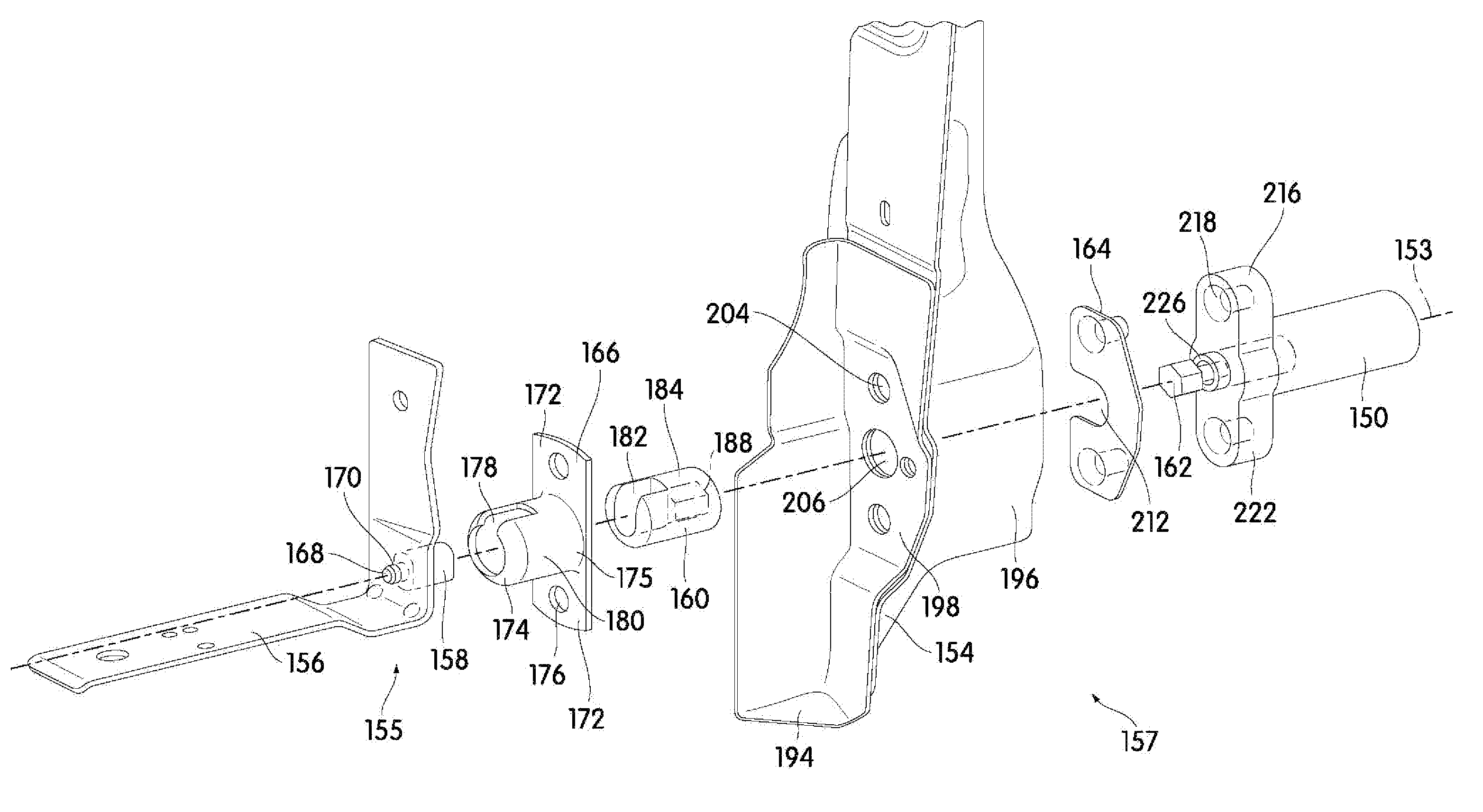
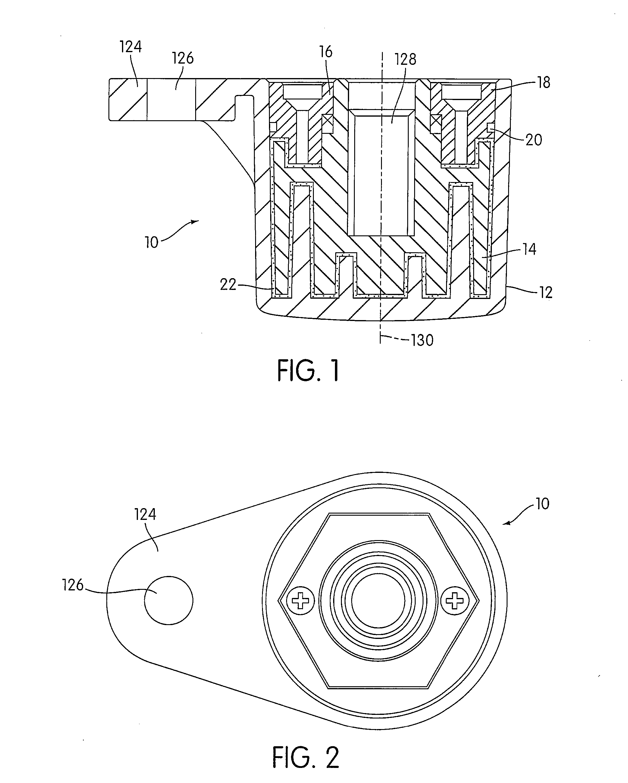
[0036]FIGS. 1 and 2 illustrate a rotary viscous damper constructed in accordance with one embodiment of the present invention. This viscous damper is provided only as an example to illustrate one way for constructing the invention, and should not be regarded as limiting.

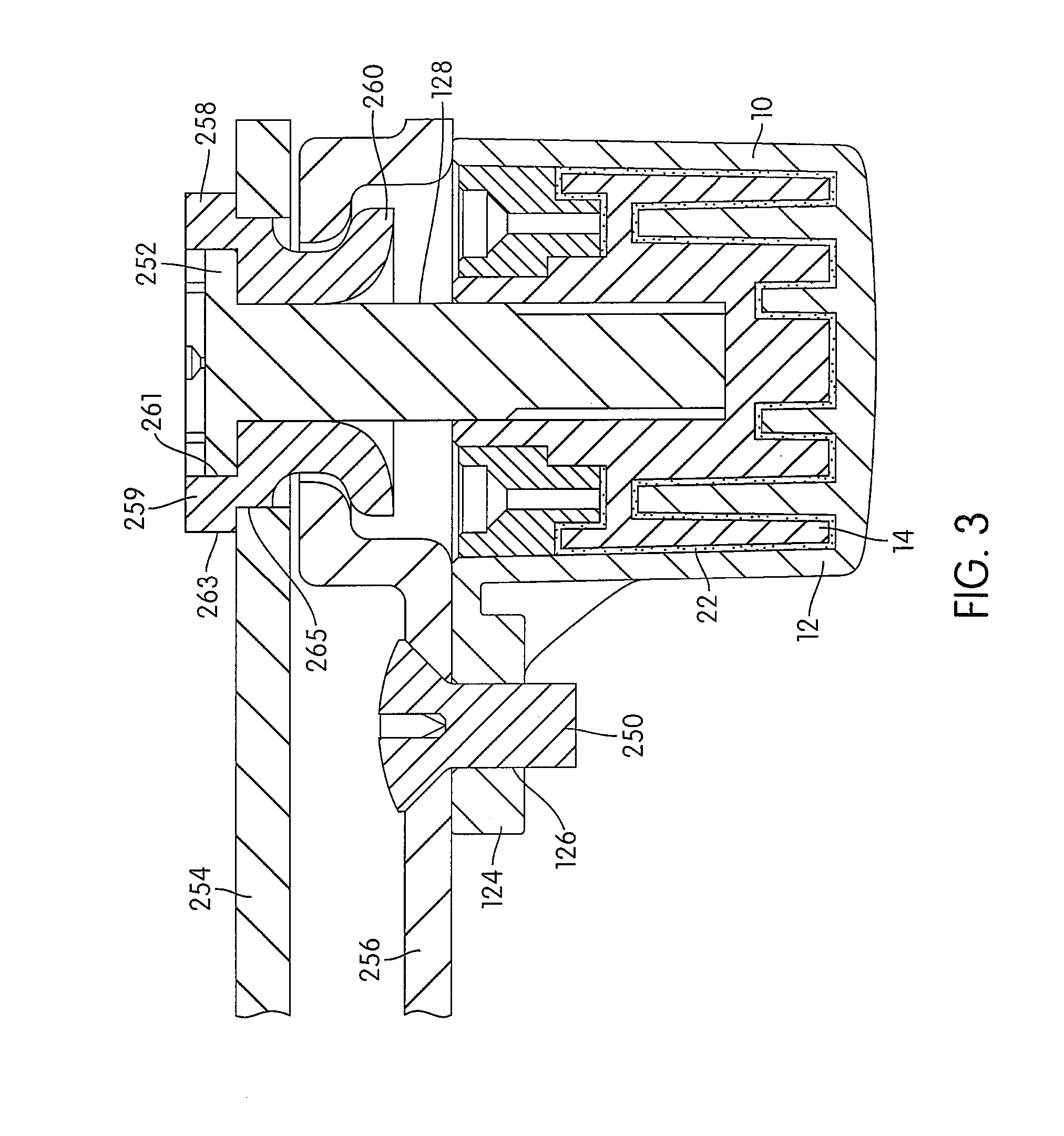
[0037]As shown in FIGS. 1 and 2, the viscous damper 10 includes a cover 12, a rotor 14, a seal 16, a seal cover 18 and an o-ring seal 20. In one embodiment, the seal 16 may also be in the form of the o-ring 20. The cover 12 and the seal cover 18 may be considered an enclosed housing. The rotor 14 is rotatably supported within the cover 12 of the viscous damper 10 and a viscous material 22 is filled in the space between the cover 12 and the rotor 14. The seal cover 18 is fixed to the open end of the cover 12 and the seal 16 is placed between the rotor 14 and the inner edge of the seal cover 18. The o-ring 20 is disposed between the outer edge of the seal cover 18 and the cover 12. The seal 16, the seal cover 18 and th...


PUM


Abstract

An assembly to pivotally connect an external vehicle closure panel to a vehicle body includes a first hinge member that is constructed to be mounted to one of the external vehicle closure panel and the vehicle body, a second hinge member that is constructed to be mounted to the other of the external vehicle closure panel and the vehicle body, a shaft that is constructed to pivotally connect the first hinge member to the second hinge member, and a viscous rotary damper. The damper includes a cover, a rotor, and a viscous material. The shaft connects to the rotor such that rotation of the external vehicle closure panel between a closing position and an opening position causes relative motion between the rotor and the cover of the viscous damper to provide a resistance for controlling the velocity of the external vehicle closure member.

Description

[0001]The present application claims priority to U.S. Provisional Application Ser. No. 60 / 978,910, filed on Oct. 10, 2007, the entirety of which is hereby incorporated herein.BACKGROUND OF THE INVENTION[0002]1. Field of the Invention[0003]The present invention relates to a viscous rotary damper that is applied to a hinge of an automotive closure system such as tailgates, doors, trunks, liftgates, decklids, etc.[0004]2. Description of Related Art[0005]Current entry / exit door systems in an automobile often use mechanical devices to provide soft stop locations or checks between a fully open position and a fully closed position, and a hard stop at the fully open position. However, the operation of these mechanical devices may be perceived to be “harsh” by the end user. It is especially difficult to control the door bounce back from the fully open hard stop location by using these mechanical devices. When the end user opens the door and moves the door into the fully open position, the sy...

Claims


Application Information

Patent Timeline
Patent Type & Authority Patents(United States)
IPC IPC(8): B60J5/00
CPCE05F5/00E05D3/145E05D5/062E05D11/1071E05D2005/067E05F3/14E05F3/20Y10T16/2771E05Y2201/21E05Y2201/254E05Y2201/266E05Y2900/531E05Y2900/538E05Y2900/546
Inventor PATZER, BRAD F.SMITH, MICHAEL D. J.MAGOVSKI, STANISLAVSHAW, DAVID W.HUNG, JOAQUIN
Owner VENTRA GRP
Why Eureka
Try Eureka