LED device for wide beam generation

a technology of led devices and wide beams, which is applied in the direction of fixed installation, lighting and heating apparatuses, instruments, etc., can solve the problems of high cost, waste of resources, waste of resources, etc., and achieve the effect of eliminating seams or optical discontinuities, high angle intensity wide beams

Active Publication Date: 2010-03-09
SIGNIFY HLDG BV
View PDF56 Cites 226 Cited by
  • Summary
  • Abstract
  • Description
  • Claims
  • Application Information

AI Technical Summary

Benefits of technology

[0023]Each array is a modular unit capable of being readily combined with a like array and further comprising a collection of arrays for scaling the intensity of the illumination pattern on the target surface without substantial modification of the illumination pattern by modular scaling of the arrays into a larger or smaller collection.
[0031]Another one of the illustrated embodiments is a luminaire for a street light to provide a predetermined illumination pattern on a street surface, the predetermined illumination pattern having a defined horizon, comprising a lighting fixture, and a plurality of planar arrays of light emitting devices disposed in the lighting fixture, each array for providing the predetermined illumination pattern on the street surface with substantial reduction of light directed from the luminaire to the horizon or above.
[0033]The lens comprises a transparent or translucent “blob-like” or dimpled-puddle shape, which produces a high angle intensity wide beam without adding any additional surface losses, either reflective or refractive than the LED would cause itself in this configuration of the invention. Almost all the energy of the LED is directed into the beam without losses much in excess of those generated by the LED without the lens deployed.
[0034]In one embodiment the lens is separate from the LED and is glued, affixed or disposed on the light source or original LED protective dome with an index matching material so as to virtually eliminate the seam or any optical discontinuity between the two. In another embodiment the lens is manufactured as the protective dome of the LED.
[0039]One major advantage of a device of the invention is the ability to generate the required beam pattern with an array of LEDs which are mounted on a flat or planar plate, which most likely would be parallel to the street or floor. Thus eliminating the need for a complex armature. The illustrated embodiment further comprises a plurality of light sources or LEDs and corresponding lenses as describe above combined into a flat array of bars or plates to provide thermal and electrical distribution required for the LEDs as well as provide means for sealing the array from environmental damage. The apparatus further comprises circuitry to drive the LEDs included in the array. It is contemplated that each of the lenses are individually rotated to create a beam pattern for the flat array that is unique from the devices themselves, including all degrees of freedom, e.g. separately determined translation, tilt and yaw for each lens. The array could comprise similarly colored LEDs, white or otherwise, or optionally various colored LEDs.

Problems solved by technology

The initial investment cost of LED illumination is expensive when compared with traditional lighting means using cost per lumen as the metric.
While this may change over time, this high cost places a premium on collection and distribution efficiency of the LED optical system.
The dazzling city lights seen from aircraft and hill tops may be romantic, but represent huge energy losses, unnecessary fuel usage, and tons of unnecessary green house gas emissions from the electrical plants needed to generate the electricity for the wasted light.
Lenses which are not coated with anti-reflective coatings also have surface losses associated with them.

Method used


Image

  • LED device for wide beam generation
  • LED device for wide beam generation
  • LED device for wide beam generation

Examples


Embodiment Construction

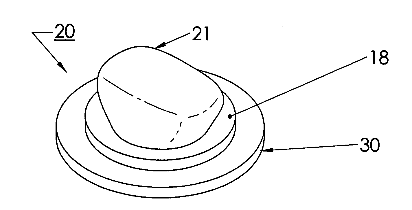
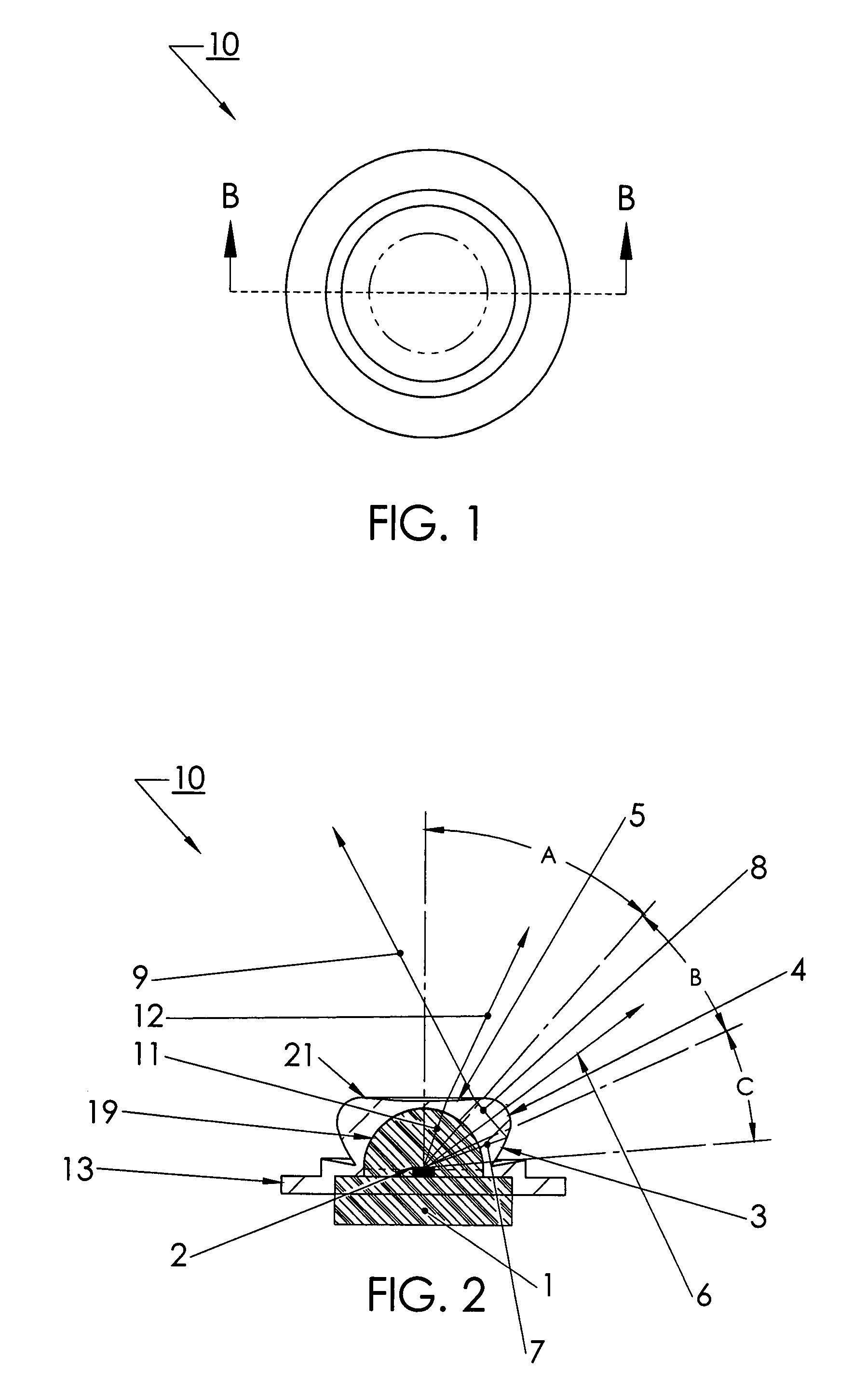
[0078]Before turning to the specifically illustrated examples shown in the drawings, we consider the various embodiments of the invention in more general terms. The illustrated embodiment of the invention uses light emitting diodes (LED), or other light sources, in a device that directs the energy from the LED into a smooth, broad beam. A broad beam can best be described as a beam which provides an illumination pattern on the surface intended to be illuminated, (e.g. the street, sidewalk, wall, etc.) that has a 50 percent maximum foot-candle measurement at an angle greater than 15 degrees from the centerline of the illumination pattern. This is referred to in the lighting field as the half-maximum point. A light source with a 15 degree half maximum measurement is also described as a 30 degree FWHM (Full Width, Half Maximum) light source.

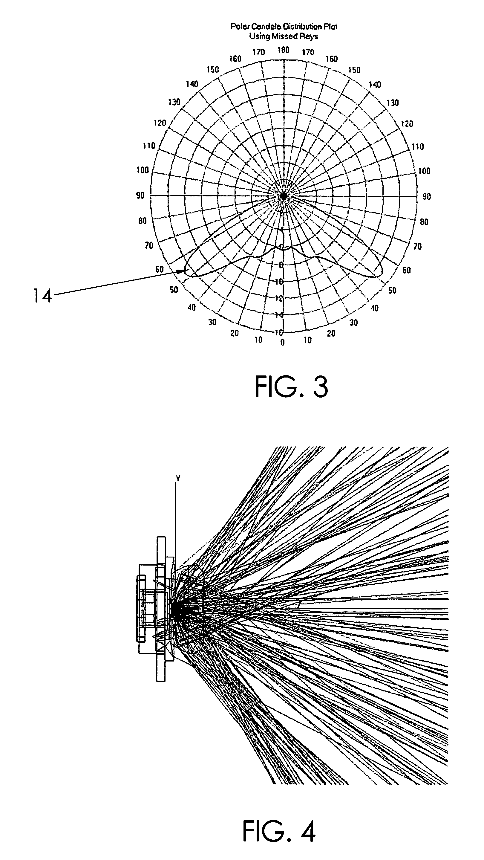
[0079]Since light energy dissipates as the square of the distance from the source and there is additionally a cosine falloff based on the angle of i...


PUM


Abstract

An apparatus and method is characterized by providing an optical transfer function between a predetermined illuminated surface pattern, such as a street light pattern, and a predetermined energy distribution pattern of a light source, such as that from an LED. A lens is formed having a shape defined by the optical transfer function. The optical transfer function is derived by generating an energy distribution pattern using the predetermined energy distribution pattern of the light source. Then the projection of the energy distribution pattern onto the illuminated surface is generated. The projection is then compared to the predetermined illuminated surface pattern to determine if it acceptably matches. The process continues reiteratively until an acceptable match is achieved. Alternatively, the lens shape is numerically or analytically determined by a functional relationship between the shape and the predetermined illuminated surface pattern and predetermined energy distribution pattern of a light source as inputs.

Description

RELATED APPLICATIONS[0001]The present application is related to U.S. Provisional Patent Application Ser. No. 60 / 777,310, filed on Feb. 27, 2006; U.S. Provisional Patent Application Ser. No. 60 / 838,035, filed on Aug. 15, 2006; and U.S. Provisional Patent Application Ser. No. 60 / 861,789, filed on Nov. 29, 2006, each of which are incorporated herein by reference and to which priority is claimed pursuant to 35 USC 119.BACKGROUND OF THE INVENTION[0002]1. Field of the Invention[0003]The invention relates to the field of apparatus and methods for using light emitting diodes (LEDs) or other light sources to generate predetermined wide profile two dimensional illumination patterns using a light source which has been optically modified to provide a corresponding wide profile beam or a flat array of multiple ones of such modified light sources.[0004]2. Description of the Prior Art[0005]The initial investment cost of LED illumination is expensive when compared with traditional lighting means us...

Claims


Application Information

Patent Timeline
Patent Type & Authority Patents(United States)
IPC IPC(8): F21V3/00F21V5/04H01L33/58
CPCF21K9/00F21S8/086F21V5/04G02B27/0012F21V13/04G02B19/0071G02B19/0028G02B19/0061F21S8/085F21W2131/103F21Y2101/02F21V31/005H01L33/58F21Y2105/16F21Y2115/10F21K9/69F21V23/005F21V7/0091F21V19/02F21V29/70
Inventor HOLDER, RONALD G.RHOADS, GREG
Owner SIGNIFY HLDG BV
Why Eureka
Try Eureka