Parts for deposition reactors

a technology of deposition reactor and parts, which is applied in the direction of chemical vapor deposition coating, coating, electrical equipment, etc., can solve the problems of particulate matter contamination, adverse effects, and degrading the purity and uniformity of deposited films

Active Publication Date: 2010-03-09
ASM INTERNATIONAL
View PDF85 Cites 229 Cited by
  • Summary
  • Abstract
  • Description
  • Claims
  • Application Information

AI Technical Summary

Problems solved by technology

Deposition results, however, can be adversely affected by the presence of particulate matter in the furnace.
In some cases, the particles can come to rest on or become incorporated into the films, thereby degrading the purity and uniformity of the deposited films.
A possible source of particulate matter contamination is material deposited on reactor surfaces.
This material can then flake off the reactor surfaces, thereby generating particulate matter that can contaminate deposited films.

Method used


Image

  • Parts for deposition reactors
  • Parts for deposition reactors

Examples


Embodiment Construction

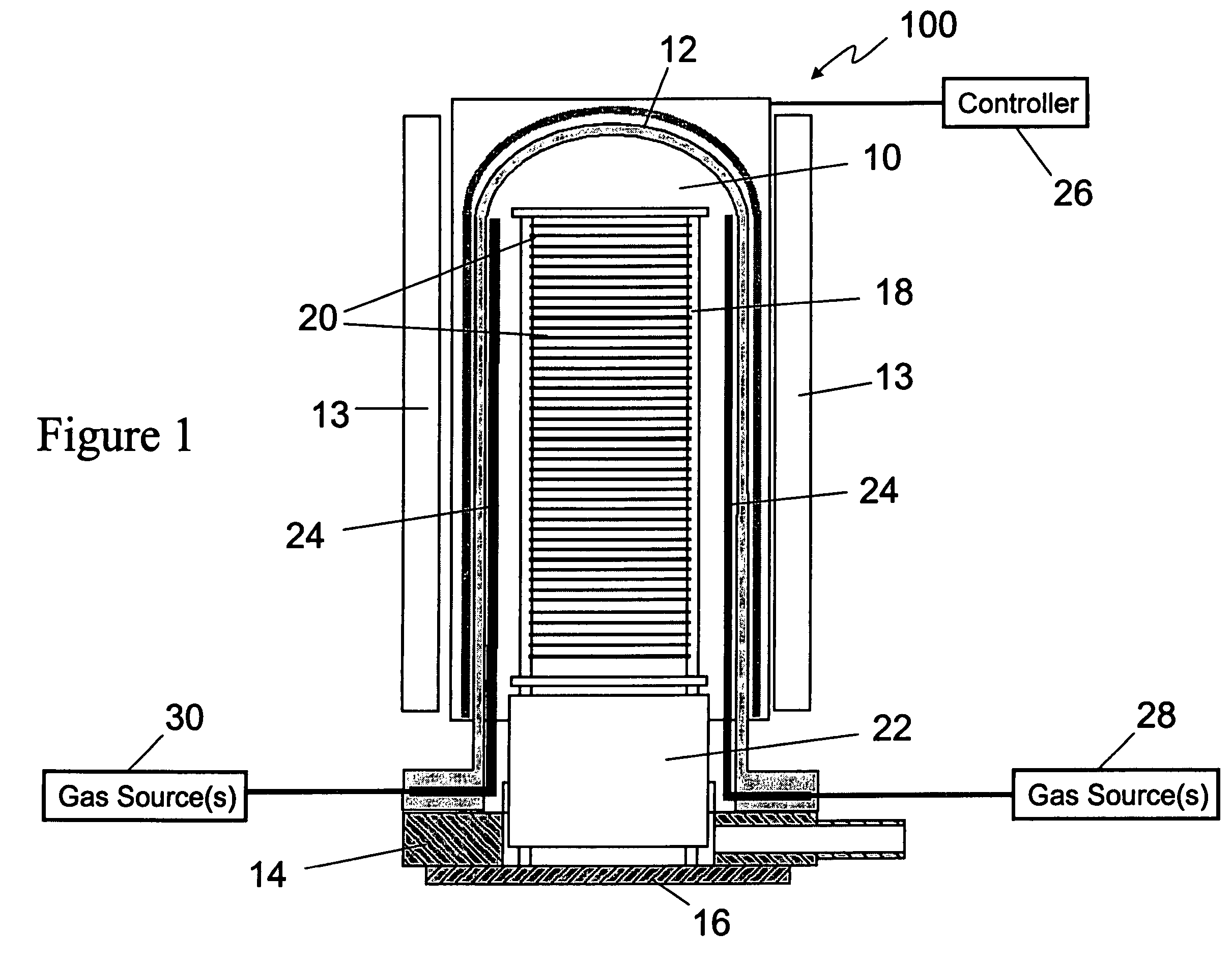
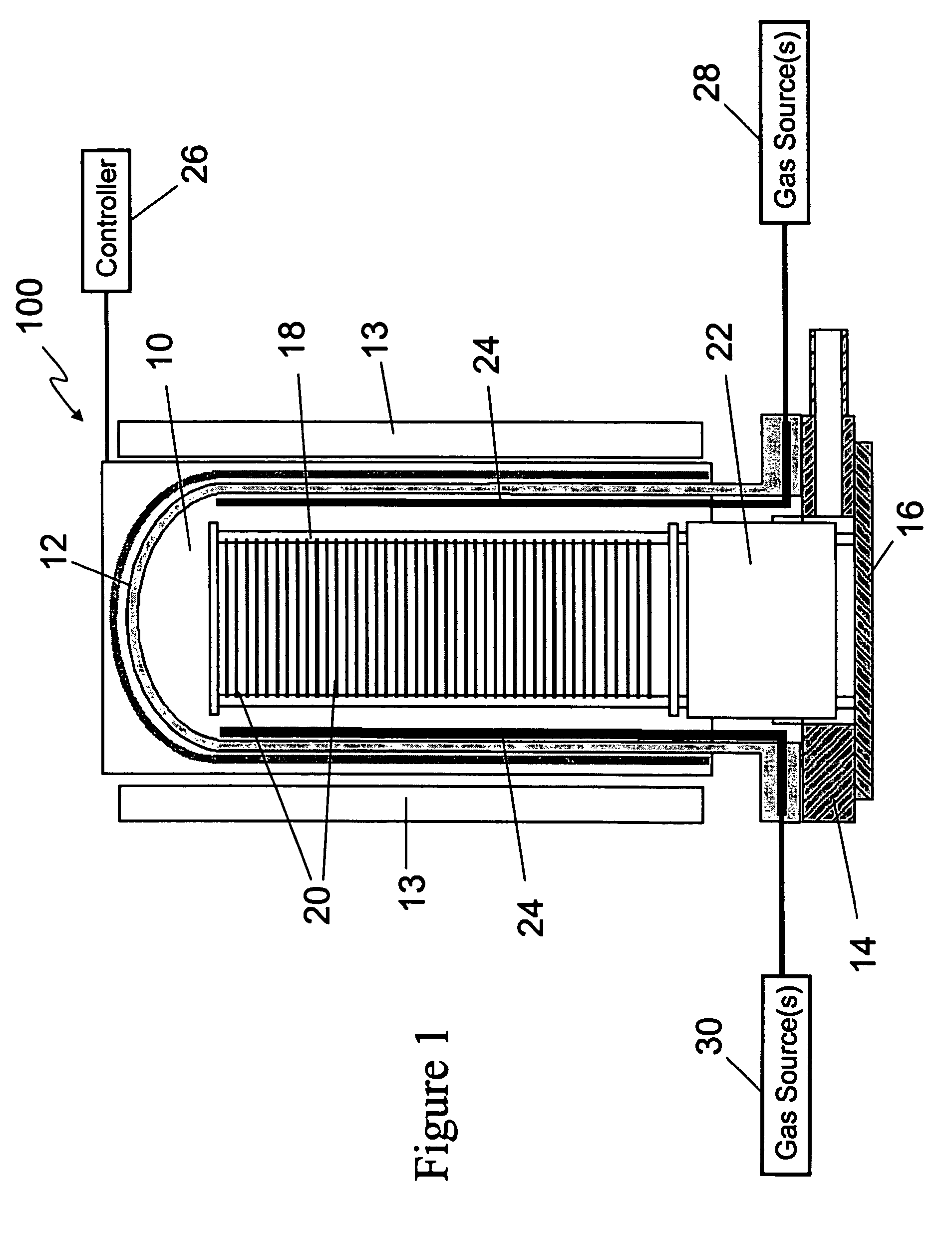
[0015]It has been found that excessively high levels of particle generation can occur during the deposition of film materials, especially some modern, newly-used film materials. These high levels of particle generation have been found to be caused by mismatches in the coefficients of thermal expansion (CTE's) between reactor parts and films that are deposited on the reactor parts. For example, when a deposited film expands at a different rate than an underlying reactor part, the films can crack and encourage the flaking of deposited material off of the reactor part. This cracking and flaking increases the particle count in a process chamber and can cause the deposited films to become contaminated with the flaked off material. The cracking and flaking has been found to be exacerbated in newer films, especially those more recently found to be suitable for formation by chemical vapor deposition in hot-wall reactors, because differences in CTE's between reactor parts and the deposited f...


PUM

PropertyMeasurementUnit
temperatureaaaaaaaaaa
temperaturesaaaaaaaaaa

Abstract

Processing methods and internal reactor parts avoid peeling and particle generation caused by differences in the coefficients of thermal expansion (CTE's) between reactor parts and films deposited on the reactor parts in hot wall CVD chambers. Conventional materials for reactor parts have relatively low CTE's, resulting in significant CTE differences with modem films, which can be deposited on the surfaces of reactor parts during semiconductor processing. Such CTE differences can cause cracking and flaking of the deposited films, thereby leading to particle generation. Reactor parts, such as boats and pedestals, which undergo large thermal cycles even in a hot wall chamber, are made of materials having a CTE greater than about 5×10⁻⁶ K−1, in order to more closely match the CTE of deposited materials, such TiN. The decreased CTE differences decrease differences between the expansion and contraction of the reactor parts and deposited films, leading to decreased cracking, flaking and, ultimately, decreased particle generation.

Description

CROSS-REFERENCE TO RELATED APPLICATIONS[0001]This application claims the priority benefit of U.S. Provisional Application No. 60 / 619,114, filed Oct. 15, 2004.[0002]This application is also related to U.S. patent application Ser. No. 11 / 096,861, filed Mar. 31, 2005, the entire disclosure of which is incorporated herein by reference.FIELD OF THE INVENTION[0003]This invention relates generally to semiconductor fabrication and, more particularly, to thermal reactors for depositing films on substrates.BACKGROUND OF THE INVENTION[0004]Hot wall reactors can be used to deposit various materials on semiconductor substrates. The substrates can be accommodated in the process chamber of the reactors and precursors can be flowed into the process chamber to deposit films of material on the substrates. For a variety of reasons, including uniformity of electrical and physical properties, high purity and uniformity is typically desired for the deposited films. Deposition results, however, can be adv...

Claims


Application Information

Patent Timeline
Patent Type & Authority Patents(United States)
IPC IPC(8): H01L21/31
CPCC23C16/4401C23C16/4581
Inventor HASPER, ALBERTOOSTERLAKEN, THEODORUS GERARDUS MARIA
Owner ASM INTERNATIONAL
Why Eureka
Try Eureka