Nitride-based semiconductor device of reduced voltage drop

a technology of nitride-based semiconductors and semiconductors, applied in the field of semiconductor devices, can solve problems such as power loss, and achieve the effect of reducing drive voltage and reducing voltage drop

Active Publication Date: 2010-03-09
SANKEN ELECTRIC CO LTD
View PDF21 Cites 4 Cited by
  • Summary
  • Abstract
  • Description
  • Claims
  • Application Information

AI Technical Summary

Benefits of technology

[0014]It will be appreciated that these achievements of the invention are accomplished merely by switching the silicon substrate from n- to p-type conductivity. No extra cost is needed for the manufacture of the improved semiconductor devices.
[0015]In some embodiments of the invention, which take the form of LEDs, the aforesaid first electrode is comprised of a transparent overlay formed on the main semiconductor region and a bonding pad placed centrally on the transparent overlay. As has been discussed in conjunction with the prior art, there is created between the bonding pad and the semiconductor region a Schottky baffier which functions to block the forward current of the LED. Should the LED be easy to overheat, as has been the case with the prior art devices of comparable design, the Schottky baffier would fail to perform its intended function to the full. Since the LED according to the invention operates with a less drive voltage, suffers less power loss, and generates less heat, than the prior art, the Schottky barrier will hardly deteriorate and keep the efficiency of light emission at a predetermined maximum throughout the expected lifetime of the LED.

Problems solved by technology

The reduction of the potential barrier leads to that of the drive voltage requirement of the semiconductor device and hence to that of power loss.

Method used


Image

  • Nitride-based semiconductor device of reduced voltage drop
  • Nitride-based semiconductor device of reduced voltage drop
  • Nitride-based semiconductor device of reduced voltage drop

Examples


embodiment

OF FIG. 4

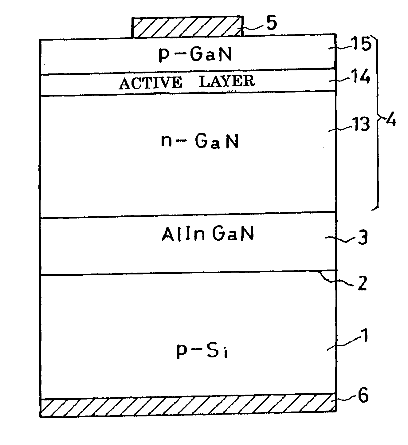
[0057]In FIG. 4 is shown another preferred form of LED according to the present invention. This alternate LED features a modified buffer region 3a, all the other details of construction being as previously set forth with reference to FIG. 1.

[0058]The modified buffer region 3a is a lamination of a first or monolayered buffer subregion 3 of n-type AlInGaN, similar to the buffer region 3 of the FIG. 1 embodiment, and, thereover, a second or multilayered buffer subregion 20. The multilayered buffer subregion 20 is a lamination of alternating two different kinds of layers 21 and 22. The first layers 21 of the second buffer subregion 20 contain aluminum whereas the second layers 22 thereof either do not contain aluminum or do contain it in a less proportion than do the first layers 21.

[0059]More specifically, the first layers 21 of the second buffer subregion 20 are made from any of the nitride semiconductors that can be defined by the following general formula, in addition to an...


PUM


Abstract

A light-emitting device has a main semiconductor region formed via an n-type AlInGaN buffer region on a p-type silicon substrate, the latter being sufficiently electroconductive to provide part of the current path through the device. Constituting the primary working part of the LED, the main semiconductor region comprises an n-type GaN layer, an active layer, and a p-type GaN layer, which are successively epitaxially grown in that order on the buffer region. A heterojunction is created between p-type substrate and n-type buffer region. Carrier transportation from substrate to buffer region is expedited by the interface levels of the heterojunction, with a consequent reduction of the drive voltage requirement of the LED.

Description

CROSS REFERNCE TO RELATED APPLICATIONS[0001]This is a continuation of Application PCT / JP2004 / 013819, filed Sep. 22, 2004, which claims priority to Japanese Patent Application No. 2003-331881 filed Sep. 24, 2003, and Japanese Patent Application No. 2004-093515 filed Mar. 26, 2004.BACKGROUND OF THE INVENTION[0002]This invention relates to semiconductor devices, and particularly to those of the class employing nitrides or derivatives thereof as semiconductors, as typified by light-emitting diodes (LEDs) and transistors.[0003]Nitride-based semiconductor devices have been known and used extensively which are built upon substrates of sapphire, silicon, or silicon carbide. Of these known substrate materials, silicon offers the advantages of greater ease of machining and less expensiveness than the others. Additionally, unlike sapphire, silicon permits doping to provide a substrate that is sufficiently electroconductive to serve as part of the main current path in the device. Offsetting the...

Claims


Application Information

Patent Timeline
Patent Type & Authority Patents(United States)
IPC IPC(8): H01L33/00H01L21/20H01L29/20H01L29/267H01L33/04H01L33/12H01L33/32H01L33/34
CPCH01L21/02381H01L21/02458H01L21/02507H01L21/0254H01L33/007H01L21/02579H01L21/0262H01L29/267H01L21/02576H01L29/2003
Inventor OTSUKA, KOJIMOKU, TETSUJISATO, JUNJITADA, YOSHIKIYOSHIDA, TAKASHI
Owner SANKEN ELECTRIC CO LTD
Why Eureka
Try Eureka