Method and apparatus for segmenting structure in CT angiography

a technology of computed tomography and segmentation structure, applied in the field of medical imaging, can solve the problems of difficult identification and segmentation of bone and vascular structures, inability to segment the structure, etc., and achieve the effect of facilitating the segmentation of the structur

Inactive Publication Date: 2010-03-09
GENERAL ELECTRIC CO
View PDF5 Cites 30 Cited by
  • Summary
  • Abstract
  • Description
  • Claims
  • Application Information

AI Technical Summary

Problems solved by technology

However, segmentation of vasculature and bone structures may be complicated by a variety of factors.
For example, in CTA, overlapping image intensities, close proximity of imaged structures, limited detector resolution, calcification, and interventional devices may make the identification and segmentation of bone and vascular structures difficult.
Because of these complicating factors, existing segmentation techniques may improperly exclude image data from the segmented structure due to poor edge recognition and / or non-homogeneities in the image data.
Such exclusions may potentially result in early or erroneous termination of the segmentation technique.
Furthermore, splits or mergers in the structure of interest may not be properly segmented by existing techniques due to these shortcomings.
Alternatively, overlapping intensity ranges and / or poor edge recognition may result in the improper inclusion of proximate background regions in the segmented structure, leading to late termination of the segmentation process.
This process may be particularly difficult in the head and neck region due to the poor bone boundaries observed via CT and other imaging modalities.
As a result, the operator may have to redraw or reset the contour repeatedly throughout the process, potentially taking over an hour to process an imaged head and neck volume.
In addition, the operator intervention may lead to inter- and intra-user variability in the segmentation of structures.
Due to the labor intensiveness of this process, the operator may attempt to reduce the processing time by limiting the process to a region or volume of interest corresponding to the location of the pathology.
Limiting the process in this manner, however, does not take full advantage of the entire set of volume data available.
Furthermore, limiting the processing to the known or suspected region of a pathology may prevent additional pathologies which are obscured from being discovered, despite the availability of the data.

Method used


Image

  • Method and apparatus for segmenting structure in CT angiography
  • Method and apparatus for segmenting structure in CT angiography
  • Method and apparatus for segmenting structure in CT angiography

Examples


Embodiment Construction

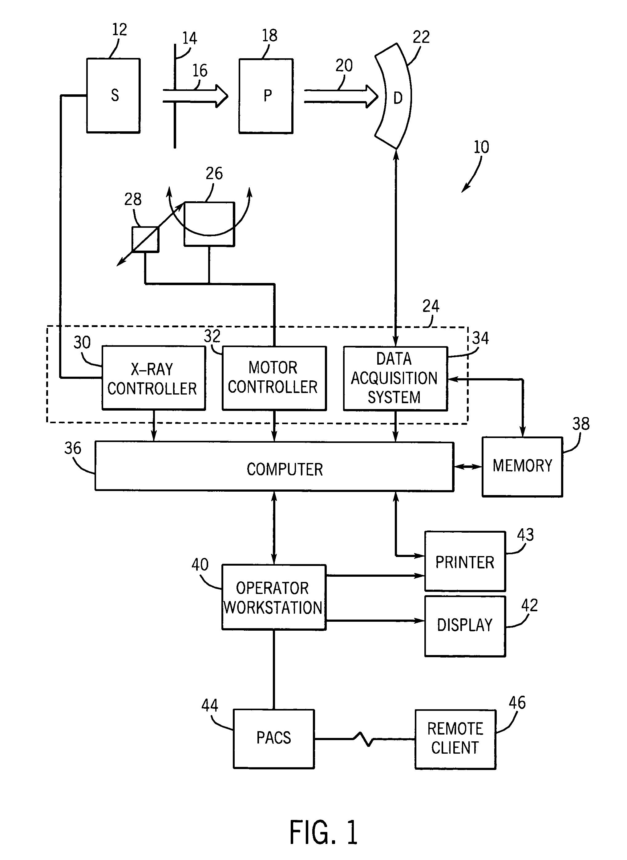
[0016]FIG. 1 illustrates diagrammatically an imaging system 10 for acquiring and processing image data. In the illustrated embodiment, system 10 is a computed tomography (CT) system designed both to acquire original image data and to process the image data for display and analysis in accordance with the present technique. Other imaging modalities which acquire image data for a volume, such as magnetic resonance imaging (MRI) or positron emission tomography (PET), may also benefit from the present techniques. The following discussion of CT systems is merely an example of one such implementation and is not intended to be limiting in terms of modality or anatomy.

[0017]In the embodiment illustrated in FIG. 1, imaging system 10 includes a source of X-ray radiation 12 positioned adjacent to a collimator 14. In this exemplary embodiment, the source of X-ray radiation source 12 is typically an X-ray tube. Collimator 14 permits a stream of radiation 16 to pass into a region in which a subjec...


PUM


Abstract

A technique is provided for automatically generating a bone mask in CTA angiography. In accordance with the technique, an image data set may be pre-processed to accomplish a variety of function, such as removal of image data associated with the table, partitioning the volume into regionally consistent sub-volumes, computing structures edges based on gradients, and / or calculating seed points for subsequent region growing. The pre-processed data may then be automatically segmented for bone and vascular structure. The automatic vascular segmentation may be accomplished using constrained region growing in which the constraints are dynamically updated based upon local statistics of the image data. The vascular structure may be subtracted from the bone structure to generate a bone mask. The bone mask may in turn be subtracted from the image data set to generate a bone-free CTA volume for reconstruction of volume renderings.

Description

BACKGROUND OF THE INVENTION[0001]The present invention relates generally to the field of medical imaging and particularly to the field of volumetric medical imaging. Specifically, the invention relates to a technique for segmenting bone and vasculature data in computed tomography.[0002]Volumetric medical imaging technologies use a variety of techniques to gather three-dimensional information about the body. For example, computed tomography (CT) imaging system measure the attenuation of X-ray beams passed through a patient from numerous angles. Based upon these measurements, a computer is able to reconstruct images of the portions of a patient's body responsible for the radiation attenuation. As will be appreciated by those skilled in the art, these images are based upon separate examination of a series of angularly displaced cross sections. It should be pointed out that a CT system produces data that represent the distribution of linear attenuation coefficients of the scanned object...

Claims


Application Information

Patent Timeline
Patent Type & Authority Patents(United States)
IPC IPC(8): A61B5/05G06K9/00A61B6/03A61B6/00G06T5/00
CPCA61B6/481A61B6/504A61B6/5252G06K9/346G06T5/50G06T7/0012G06T7/0081G06T7/0083G06T7/0097A61B6/032A61B6/4085G06K2009/00932G06K2209/05G06T2207/10081G06T2207/20012G06T2207/20141G06T2207/20156G06T2207/20224G06T2207/30008G06T2207/30101G06T7/11G06T7/12G06T7/174G06T7/187G06V40/14G06V10/273G06V2201/03
Inventor SURYANARAYANAN, SRIKANTHMULLICK, RAKESHMALLYA, YOGISHAKAMATH, VIDYA PUNDALIKNAGARAJ, NITHIN
Owner GENERAL ELECTRIC CO
Why Eureka
Try Eureka