Slotted hulls for boats

a technology for boats and hulls, applied in the field of hulls of boats and ships, to achieve the effects of enhancing stability, safety and comfort, and enhancing operation and use experien

Inactive Publication Date: 2010-03-16
MILLER BUDDIE GORDON
View PDF14 Cites 9 Cited by
  • Summary
  • Abstract
  • Description
  • Claims
  • Application Information

AI Technical Summary

Benefits of technology

[0028]Extended keels under the hull: These bring the penalties of a) increased weight; b) increased wetted-surface / drag; c) increased structural demands on the hull; d) increased power-consumption; e) increased draft.
[0086]The multiplicity of ‘spread-apart feet’ of the Slotted Hull of this invention would impart greatly enhanced stability, safety and comfort levels to the hull and commensurately enhance the operation and use experience. This is accomplished in a manner that is elegant in concept and design; simple, uncomplicated and inexpensive in manufacture; has minimal maintenance requirements; and is passive, straightforward and intuitive in operation and use.

Problems solved by technology

A major undesirable characteristic of boats is their predisposition to roll (side-to-side) and to pitch (fore-and-aft) under the influence of wind and / or waves and / or internal movement of weighty objects.
This undesirable motion is exacerbated by the fabrication of tall and weighty superstructures, including: cabins, flying-bridges, masts, sails and rigging, to boat hulls.
In severe or extreme situations, this predisposition has been the cause of countless loss of lives and boats.
These bring the penalties of:—a) increased underwater drag on the hull; b) collision hazard with flotsam; c) significant power requirement for their operation; d) significant capital cost and maintenance requirement of complex machinery; e) weight addition to the boat; g) compromise in the watertight integrity of the hull because of their through-hull assembly.“Flopper-Stoppers”: Discs or planks of large surf area, hung horizontally below the water surface, on both sides of a boat hull and using their resistance to uplift through the water, to counteract the rolling action of the boat.
This however brings the penalties of: a) decrease in streamlining and commensurate increase in drag (resistance) through the water and air; b) increased volume & weight & displacement for a given length of boat; c) much greater difficulty in recovery from a capsize situation.Increased Floatation at Hull Ends: This is usually accomplished by one or more of the following devices:—i) Significant flaring (widening) of the bow sections of the hull.ii) Keeping the bow and stern sections of the hull substantially empty or very lightly loaded.iii) Bulbous-Bow: the fabrication of a substantial, elongated bulb protruding forward from the underwater section of the hull bow.iv) Longitudinal centralization of a major weight components (engines, fuel tanks, water tanks) within the hull.Singly or in combination, these devices present the penalties of: a) having principal effect mainly against the pitching and much less so against the rolling tendency of the boat; b) significantly increased water-resistance (drag) at the bow of the boat; c) sacrifice of otherwise useable interior space within the boat.Multihulls: Conventional catamarans (2 hulls) and trimarans (3 hulls) do present the major advantage of significantly superior lateral stability versus monohulls of similar length.
This benefit however, comes with the penalties of:—a) substantially increased beam (width) of the whole boat (typically one-half of the overall length of the boat); b) increased windage since the boat superstructure is so much more voluminous and more difficult to streamline; c) requiring almost double the docking-space as a monohull of similar length; d) unfavourable aesthetics to most boat-owners; e) significantly increased cost of manufacture; f) significantly increased mechanical stresses at the interconnecting points; g) sensitivity to weight-loading; h) sensitivity to wave-slap under the bridge(s) connecting the individual hulls; i) difficulty in road-trailering because of their substantial width; j) susceptibility to pitchpoling and to diagonal-capsize; l) extreme difficulty in recovering from a capsize situation.

Method used


Image

  • Slotted hulls for boats
  • Slotted hulls for boats
  • Slotted hulls for boats

Examples


Embodiment Construction

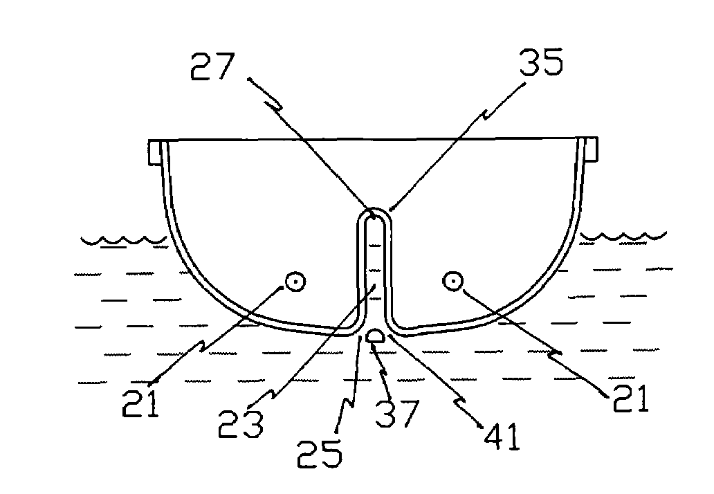
[0121]The straightforward simplicity of the functional element—a slot through-along or through-across, a boat hull—provides for utmost simplicity of construction as is illustrated in FIG. 1 of the drawings. Essentially all that is required is a fabricated or molded hollow trunk which would create and enclose the slot. This could quite easily be fabricated by a boat-builder of basic skill and using any of the common boat-building materials: wood / steel / aluminum / composites / etc, or a combination of any of these materials.

[0122]The slot would extend along most or all of the length of the hull and would extend vertically from the lowest practical level within the hull to a top level somewhat above the highest anticipated water-level about the hull.

[0123]The slot would require at least one aperture to its lowest extremity, such aperture(s) of sufficient open-area as to permit the easy ingress of water from beneath the hull.

[0124]The slot would further require at least one aperture venting ...


PUM


Abstract

A boat hull providing substantially enhanced stability, safety and comfort over conventional boat hulls in common use, incorporating at least one relatively narrow, more-or-less vertical slot (23) running longitudinally and / or laterally through the hull of the boat and positioned so that the slot(s) (23) intersects a major portion of the depth of the water displaced by the boat hull. The slot(s) (23) may be fully or partially closed at any of its fore-end (31) or aft-end (33) or bottom-edge (25).

Description

TECHNICAL FIELD[0001]This invention relates to the hulls of boats and ships.BACKGROUND ART[0002]For the purposes of this Application the term “boat” shall be used and shall be construed to include all waterborne vessels including but not necessarily limited to: boats, ships, yachts, barges, canoes, kayaks, submarines, catamarans, trimarans, etc.[0003]A common feature of traditional boats, is that they are based on the unit-body principle, that is, a hull-bottom with a single continuous skin, resting partially submerged at the surface of the water and displacing a single coherent body of water. Multihull boats (catamarans and trimarans) employ 2 or 3 respectively of such unit-body hulls, spaced apart from each other and held in juxtaposition by shared, rigid deck-beams. Submarines incorporate a completely continuous skin (monocoque) and operate either fully or partially submerged.[0004]A major undesirable characteristic of boats is their predisposition to roll (side-to-side) and to p...

Claims


Application Information

Patent Timeline
Patent Type & Authority Patents(United States)
IPC IPC(8): B63B1/00B63B1/32B63BB63B39/00B63B39/06
CPCB63B39/00B63B39/06B63B2039/067
Inventor MILLER, BUDDIE GORDON
Owner MILLER BUDDIE GORDON
Why Eureka
Try Eureka