Fluid rotation system for a cavitation chamber

a technology of cavitation chamber and fluid rotation system, which is applied in the direction of machines/engines, liquid fuel engines, positive displacement liquid engines, etc., can solve the problems of not revealing any means of stabilizing bubbles, many aspects of phenomena that have not yet been characterized, and not revealing any means of stabilizing bubble movement, etc., to achieve the effect of more stable bubbles

Inactive Publication Date: 2010-03-16
BURST ENERGIES INC
View PDF20 Cites 13 Cited by
  • Summary
  • Abstract
  • Description
  • Claims
  • Application Information

AI Technical Summary

Benefits of technology

[0012]The present invention provides a system for achieving bubble stability within a cavitation chamber. The system includes an impeller assembly, the impeller assembly having at least one impeller located within the cavitation chamber. A motor, coupled to the impeller by a drive shaft, rotates the impeller thereby causing bubbles within the cavitation chamber to move toward the impeller's axis of rotation. As a consequence, the bubbles become more stable. Preferably the axis of rotation of the impeller is positioned in a substantially horizontal plane, thus allowing the rotating impeller to counteract the tendency of the bubbles to drift upward and to accumulate on the upper, inner surfaces of the cavitation chamber. Associated with the cavitation chamber is at least one cavitation driver. If desired, a cavitation fluid circulatory system can be coupled to the cavitation chamber.
[0013]In at least one embodiment of the invention the impeller is rotated continuously throughout the cavitation process. Alternately, impeller rotation can be stopped prior to cavitating the bubbles within the cavitation chamber. In this instance the impeller can be stopped, and if desired locked, at a specific rotational position, thus minimizing possible interference between the impeller and the source of the cavitation energy.
[0015]In at least one embodiment of the invention, the impeller assembly is comprised of a two-bladed impeller. Alternate embodiments use impellers with different numbers of blades. The primary constraint placed on impeller configuration is to minimize turbulence which may result as the impeller blade(s) moves through the cavitation fluid.

Problems solved by technology

Although it is generally recognized that during the collapse of a cavitating bubble extremely high temperature plasmas are developed, leading to the observed sonoluminescence effect, many aspects of the phenomena have not yet been characterized.
U.S. Pat. No. 5,659,173 does not disclose any means for stabilizing bubbles within the cavitation zone.
The application does not disclose any means of stabilizing the movement of the injected bubbles or positioning the bubbles within the pressure vessel.
Although a variety of sonoluminescence systems have been designed, typically these systems suffer from a variety of shortcomings due to the inherent instability of the cavitating bubbles.

Method used


Image

  • Fluid rotation system for a cavitation chamber
  • Fluid rotation system for a cavitation chamber
  • Fluid rotation system for a cavitation chamber

Examples


Embodiment Construction

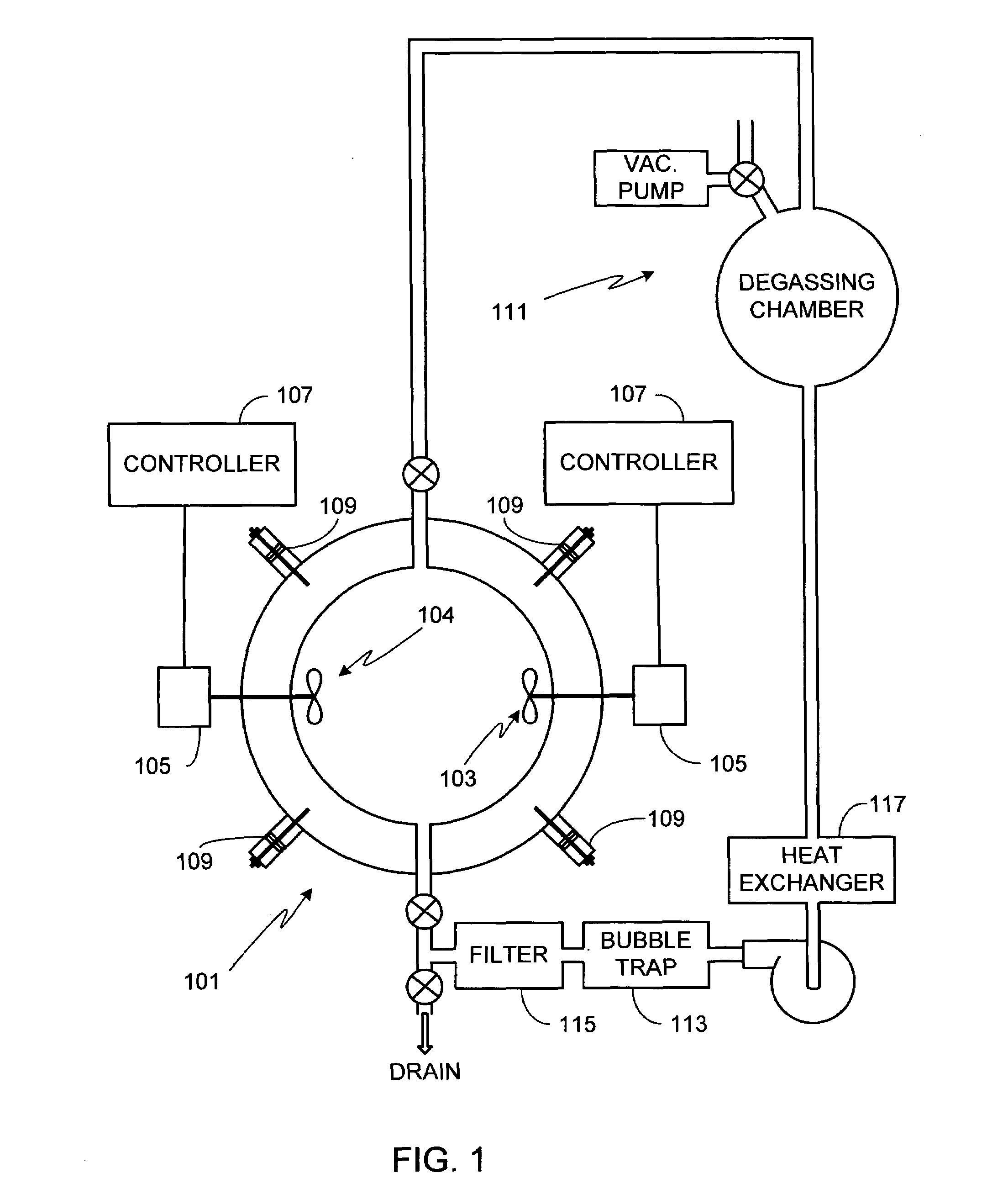
[0035]FIG. 1 is a conceptual illustration of the principal elements of the invention implemented in an exemplary embodiment. More specifically, the invention is fitted within a sonoluminescence cavitation chamber 101, hereafter referred to as simply a cavitation chamber. The invention uses at least one impeller 103, and in at least one embodiment a pair of impellers 103 / 104, to stabilize and axially center bubbles within the cavitation chamber. If a pair of impellers is used, preferably the axes of the two impellers are coaxial as shown. Each impeller shaft is attached to a motor 105 and a motor controller 107. It will be appreciated that in the description that follows unless a specific embodiment is being discussed with a particular impeller arrangement, the general description refers to both single impeller and multiple impeller embodiments.

[0036]Impeller 103, alternately impellers 103 / 104, serve many purposes. First, the impeller(s) helps to keep the cavitating bubbles away from...


PUM

PropertyMeasurementUnit
thicknessaaaaaaaaaa
diameteraaaaaaaaaa
diameteraaaaaaaaaa

Abstract

A system for achieving bubble stability within a cavitation chamber is provided. The system includes an impeller assembly, the impeller assembly having at least one impeller located within the cavitation chamber. A motor, coupled to the impeller by a drive shaft, rotates the impeller thereby causing bubbles within the cavitation chamber to move toward the impeller's axis of rotation. As a consequence, the bubbles become more stable. Preferably the axis of rotation of the impeller is positioned in a substantially horizontal plane, thus allowing the rotating impeller to counteract the tendency of the bubbles to drift upward and to accumulate on the upper, inner surfaces of the cavitation chamber. The impeller can be rotated continuously throughout the cavitation process or stopped prior to cavitating the bubbles within the cavitation chamber. In the latter scenario, the impeller can be stopped, and if desired locked, at a specific rotational position, thus minimizing possible interference between the impeller and the source of the cavitation energy. The impeller can be shaped to correspond to the inner surface of the cavitation chamber, for example spherically or cylindrically, and can utilize multiple impeller blades.

Description

FIELD OF THE INVENTION[0001]The present invention relates generally to cavitation systems and, more particularly, to a system for stabilizing bubbles within a cavitation chamber via fluid rotation.BACKGROUND OF THE INVENTION[0002]Sonoluminescence is a well-known phenomena discovered in the 1930's in which light is generated when a liquid is cavitated. Although a variety of techniques for cavitating the liquid are known (e.g., spark discharge, laser pulse, flowing the liquid through a Venturi tube), one of the most common techniques is through the application of high intensity sound waves.[0003]In essence, the cavitation process consists of three stages; bubble formation, growth and subsequent collapse. The bubble or bubbles cavitated during this process absorb the applied energy, for example sound energy, and then release the energy in the form of light emission during an extremely brief period of time. The intensity of the generated light depends on a variety of factors including t...

Claims


Application Information

Patent Timeline
Patent Type & Authority Patents(United States)
IPC IPC(8): B01F11/00
CPCB01D19/0036
Inventor TESSIEN, ROSS ALAN
Owner BURST ENERGIES INC
Why Eureka
Try Eureka