Shape memory self-ligating orthodontic brackets

a self-ligating, orthodontic technology, applied in the field of orthodontic brackets, can solve the problems of increasing bracket costs and size, reducing bracket aesthetics, and providing additional structure, and reducing the aesthetics of brackets, so as to facilitate the sliding movement of archwires, enhance the aesthetic appearance of orthodontic brackets, and reduce friction.

Inactive Publication Date: 2010-03-16
NICHOLSON JAMES A
View PDF27 Cites 26 Cited by
  • Summary
  • Abstract
  • Description
  • Claims
  • Application Information

AI Technical Summary

Benefits of technology

[0025]To reduce friction between an archwire and the orthodontic brackets of the present invention, the brackets, and / or archwire retainers, except the bonding mesh pads of the brackets, may be coated with a polytetrafluoroethylene (PTFE) material such as Teflon™, thermosetting polymer or other polymeric coatings with or without a coupling agent which form a smooth surface between the bracket and an archwire. To promote adherence of the coating, the brackets may be physically treated such as by a blasting process, chemical etching or the like. Archwires associated with the brackets and / or archwire slot inserts and flanges of the present invention may also be similarly coated.
[0034]Welding or otherwise attaching the shape memory retainers to the archwire side of the tie wings of metal brackets will create an aesthetic metallic self-ligating bracket. The attachment of shape memory retainers to ceramic or other non-metallic brackets by welding or likewise attaching the shape memory retainers to the occlusal aspects of current steel archwire inserts of ceramic brackets will produce an aesthetic ceramic bracket that is self-ligating. The orthodontist will also be able to attach colorful elastic, elastomeric ties and power chains to these twin self-ligating brackets that are pleasing to the patient.

Problems solved by technology

Unfortunately, the additional structure not only increases bracket costs and size, but also decreases bracket aesthetics and provides additional structure for trapping food and bacteria.
Orthodontists are faced with many treatment difficulties as they bond orthodontic brackets to a patient's teeth and move them from crooked and irregular malocclusion positions to their ideal positions.
Useful areas may be small with access thereto very restricted, in which case, large brackets are not used successfully; whereas, smaller and compact twin type brackets can be placed in small areas and have enjoyed exceptional popularity among Orthodontists.
Complete archwire engagement of the brackets on the teeth during various stages of orthodontic treatment is important but may not be possible.
With single wing brackets or brackets without tie wings, it is extremely difficult to accomplish partial engagement successfully and this can result in an uncontrolled and unsatisfactory tooth movement.
It is difficult to place such attachments on single wing style brackets and extremely difficult to place them on brackets without tie wings, however, a twin bracket configuration having four tie wings permits the Orthodontist to easily place such attachments and satisfactorily accomplish different aspects of a treatment.
The more points of contact between the archwire and a bracket slot during this process the greater the friction, which results in slower tooth movement and makes the treatment take longer.
Elongated single wing brackets have increased friction resisting tooth movement and thus treatment is lengthy and more complicated to complete.
Another major challenge of orthodontic treatment is the cleanliness of the brackets and areas where they are bonded or banded to the teeth.
It is difficult for patients to clean areas adjacent to brackets and tooth surfaces.
The use of larger single wings brackets makes it much harder for patients to keep their braces clean.
The process of tying and untying every bracket to secure the archwire is a tedious and laborious procedure that must be repeated each time a new archwire is placed or removed.
This process is time consuming and uncomfortable for the patient and inefficient for the Orthodontist.
Because the current self-ligating brackets on the market are not a true twin bracket design, they have serious limitations such that they are bulky and cumbersome to use in the small confines of the oral cavity.
The flexibility, shape memory effect, and superelastic nickel-titanium material has not, however, been used to construct a true twin bracket that looks and is shaped like the traditional stainless steel twin brackets.

Method used


Image

  • Shape memory self-ligating orthodontic brackets
  • Shape memory self-ligating orthodontic brackets
  • Shape memory self-ligating orthodontic brackets

Examples


Embodiment Construction

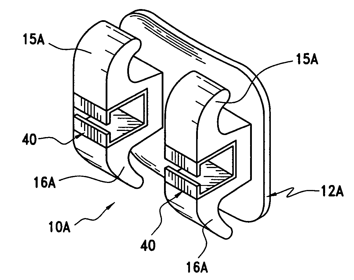
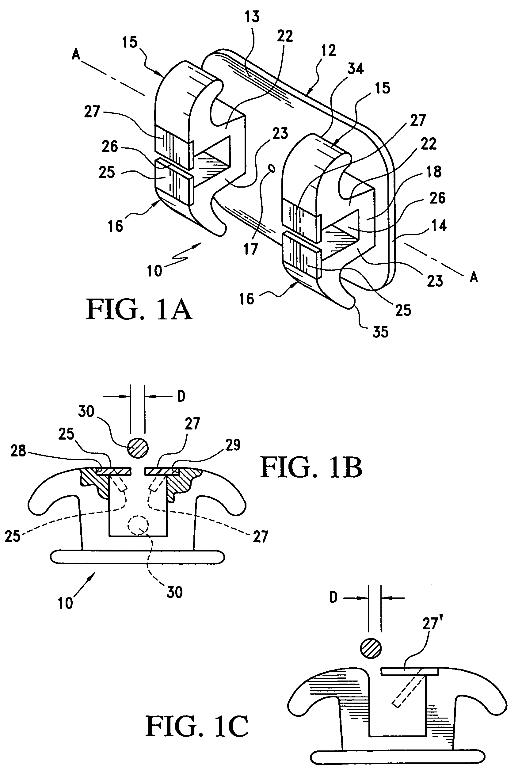
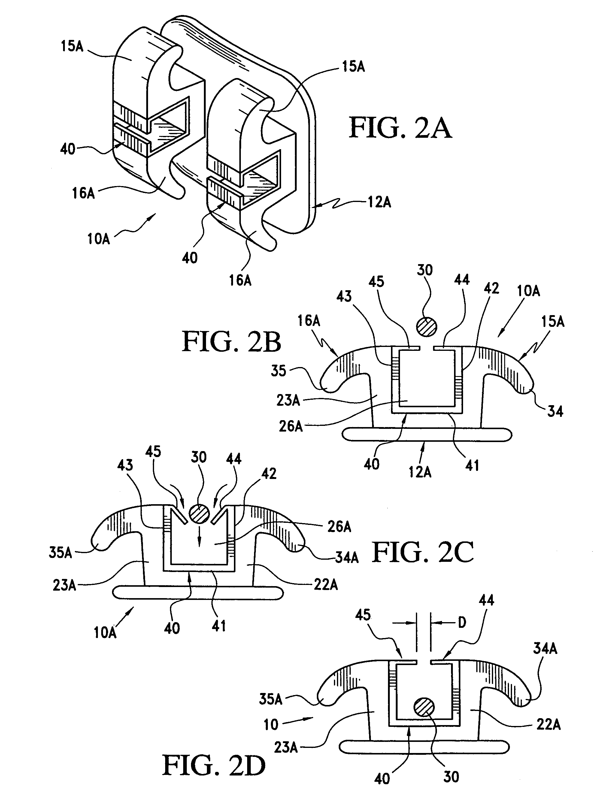
[0053]With continued reference to drawing FIGS. 1A-1C, a first embodiment of orthodontic bracket 10 of the present invention includes a contoured base 12 having a front surface 13 and tooth engaging surface 14. The rear surface 14 is generally slightly concavely contoured so as to match the surface contour of a patient's tooth.

[0054]The orthodontic bracket further includes two pair of spaced opposing tie wings 15 and 16 which are shown as being spaced on opposite sides of a central recess 17 which is formed generally centrally of the front surface of the bracket base 12. The recess 17 is used to facilitate alignment of the bracket relative to a patient's tooth using an instrument such as a Boone gauge. As opposed to the recess 17, a linear groove may be provided in the front surface 13 of the bracket base for facilitating alignment, see the embodiment of FIG. 4B at 17B.

[0055]Each pair of tie wings includes a base portion 18 from which extend posts 22 and 23. The generally parallel p...


PUM


Abstract

Self-ligating orthodontic brackets with archwire retainers formed of materials exhibiting shape memory. Each bracket which includes a base from which extends two spaced and opposing pairs of tie wings each pair of which define an archwire guide slot therebetween. The retainers include at least one flange to retain an archwire within the archwire guide slot but which is yieldable to permit insertion and / or removal of the archwire relative to the archwire guide slots. Portions of the brackets and / or retainer may be coated to reduce friction between the archwire and the bracket and to promote aesthetics and overall bracket appearance.

Description

BACKGROUND OF THE INVENTION[0001]1. Field of the Invention[0002]This invention is generally directed to orthodontic brackets for use in aligning teeth and more specifically to self-ligating orthodontic brackets that use shape memory metallic alloy or non-metallic resin or polymer archwire slot retainers, including inserts and / or retainer flanges, that may be inserted and welded or otherwise attached to metallic or non-metallic brackets which include two pair of opposing tie wings which are spaced relative to one another to define archwire slots therebetween. The retainers serve to selectively and guidingly receive and retain an archwire within the archwire guide slots defined by each pair of opposing tie wings.[0003]2. Brief Description of Related Art[0004]Generally, there are two basic styles of orthodontic brackets. A first style is known as a single wing wherein a pair of opposing elongated tie wings extend upwardly from a bracket base and are spaced to define an archwire guide s...

Claims


Application Information

Patent Timeline
Patent Type & Authority Patents(United States)
IPC IPC(8): A61D3/00
CPCA61C7/28A61C7/141A61C2201/007
Inventor NICHOLSON, JAMES A.
Owner NICHOLSON JAMES A
Why Eureka
Try Eureka